You are using an out of date browser. It may not display this or other websites correctly.
You should upgrade or use an alternative browser.
You should upgrade or use an alternative browser.
GTrr 2.0 - With pictures now! *closed*
- Thread starter Timppaq
- 106 comments
- 20,545 views


Timppaq
Premium
- 5,137

- Helsinki
- GTP_Timppaq
Aaand I'm back on this.. 
So some may remember when I last year tried to design & build a new rig for me.. and so I did too in the end.
Now it's time to make it cheaper, better & prettier (I hope)  ...I think I learned a few good lessons from the previous one, when this:
...I think I learned a few good lessons from the previous one, when this: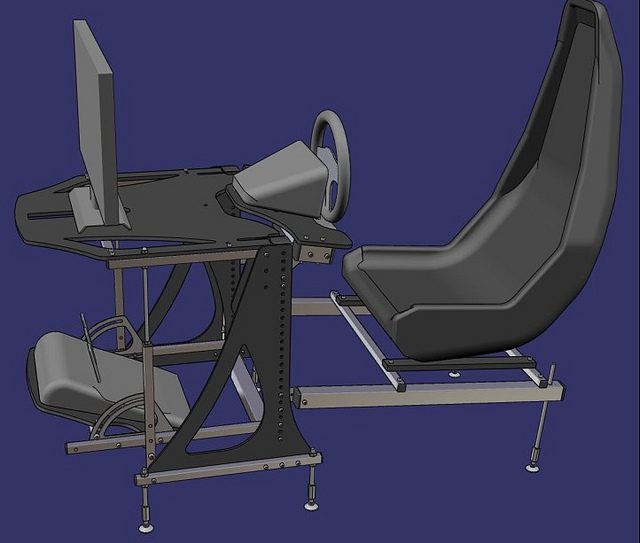
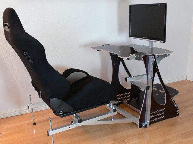
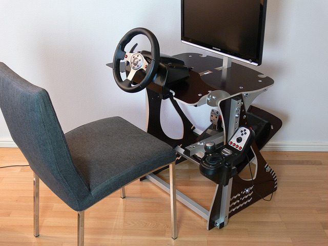
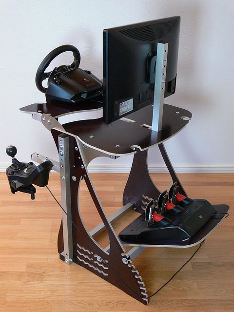
Turned into this in real life:

.
.
.
.
.
So now I finally got into refining the design with the new ideas & experiences gained from the "1.0" build.
My goal this time is:
- fewer parts in most portions
- same kind of adjustability
- improved ease of use
- more eye pleasing
- easier access (at least a little)
- fewer parts in most portions
- same kind of adjustability
- improved ease of use
- more eye pleasing
- easier access (at least a little)
This would hopefylly mean it's cheaper and much easier to build as well.
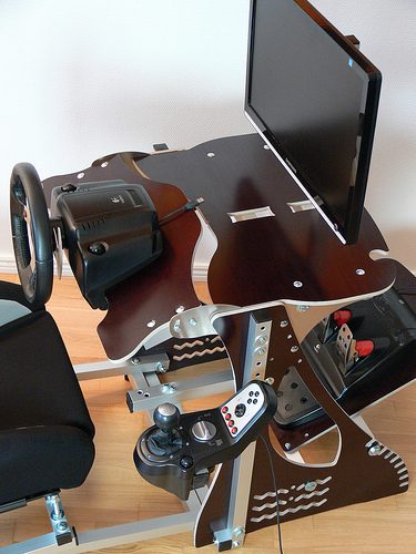
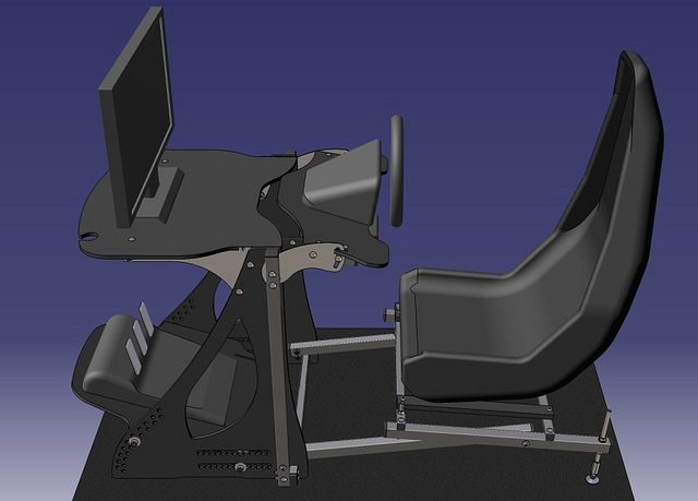
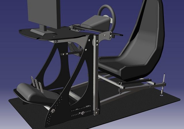
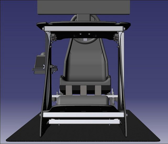
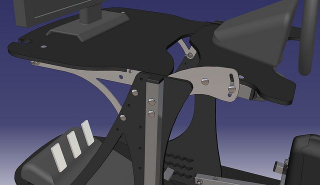
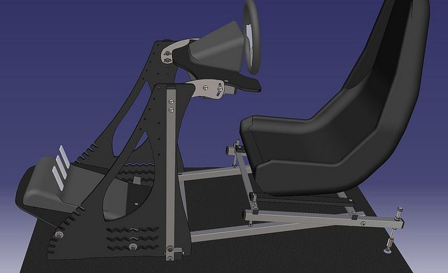
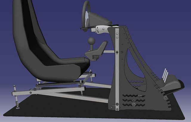
I only just today got the model ready in principle, so there are still a few details that need changing / removing / adding. But the general solutions are pretty close to what I have in mind at the moment, although some things might be more on the fence than others. Anyway, wanted to post a few preview pics here to get started and so you can hopefully give some constructive comments.. as last time proved, every bit of feedback (good or bad) is helpful in the end & appreciated as well. 👍
here's the few pics I snapped before giving it a rest for tonight:
Pic 1
Pic 2
Pic 3
Pic 4
Pic 5
Pic 6
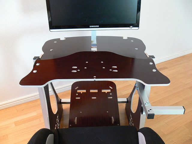
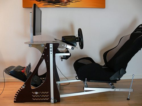
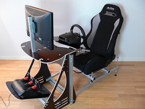
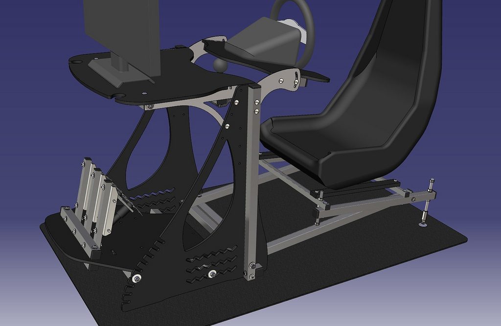
So, you still can adjust (but more easily now):
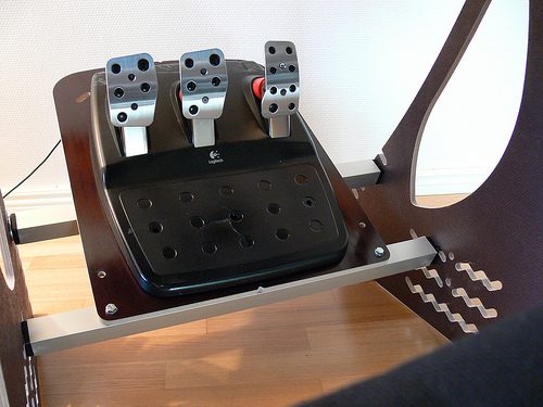
- pedals angle (loosen & tighten 2 screws)
- pedals distance (loosen & tighten 2 screws)
- pedals height (remove & fasten 2 screws)
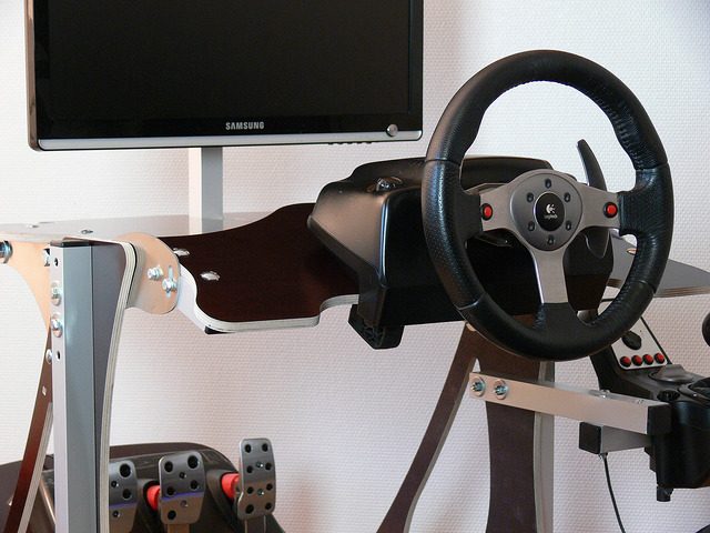
- wheel angle (loosen & tighten 2 screws)
- wheel height (loosen & tighten 2 screws)
- seat angle (adjust with M10 nuts)
- seat height (adjust with M12 nuts)
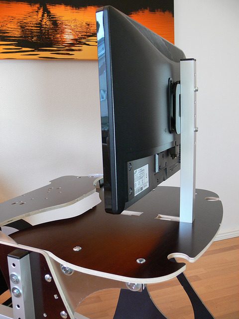
- screen height (remove & fasten 4 screws)
***CHECK MY LAST POST WITH PICS FOR THE LATEST STATE OF THE 3D MODEL***
Any questions, doubts, I'd be happy to answer / discuss.
******************************************************************************
The real 2nd post:
Aren't the new pedals often internally reversable? T500 RS / Fanatec CSRE Pedals? But sure enough it's a fair point for G25 / CSP's. I think you basically just need something in a 90 degree angle compared to the pedal board, so you still have the same adjustments. Should be possible.. pics to follow.
Last edited:
- 1,326

- SC
I wish i had a fraction of a percent of your modeling skills.
+1 I'm more impressed with the computer model than the actual thing, neat work. So much adjustability, can you just never find the right position to get comfortable? lol
Last edited:

Timppaq
Premium
- 5,137
- Helsinki
- GTP_Timppaq
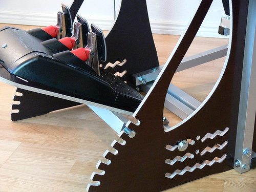
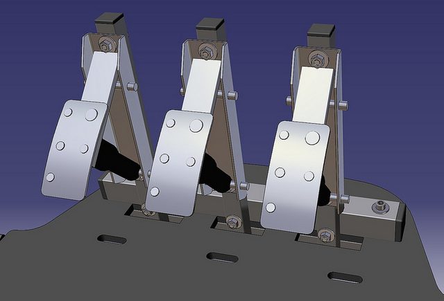
Here's the first go for the reversed pedals (ala G25):
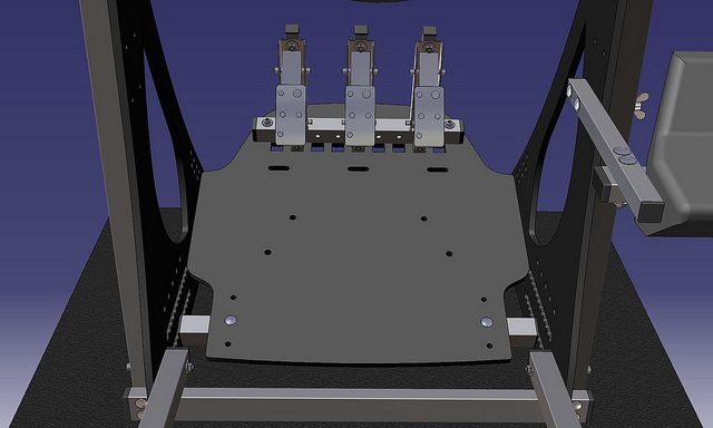
- vertical poles go through the plywood with a tight fit (more stable [see Pic 5], eliminates possible swinging to any direction - with longer vertical poles also individual pedal height could be adjusted)
- cross directional position adjustable (each pedal individually - preset slots)
- angle / height / distance adjustments still usable
Other:
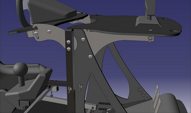
- added vertical adjustment holes for shifter
- added vertical adjustment holes for screen
- added 3rd height option for pedals
- wheel mount ply slightly reshaped
- reshaped the screen support (steel)
- changed the wheel support plates (steel) to the inner side of the plywoods
Last edited:
- 2,239
- caswellhouse
Fir me its more natural. Cant quite explain it but my throttle control and braking consistency definetly improved after I inverted my pedals. I also found i was missing less shifts.
But it is really all what you are comfortable with, and driving position plays a large part as well. Some seating positions ( f1 style for ex) are better with angled floor mounts as hung pedals may cause to much leg strain by having to stretch further for full pedal press.
But it is really all what you are comfortable with, and driving position plays a large part as well. Some seating positions ( f1 style for ex) are better with angled floor mounts as hung pedals may cause to much leg strain by having to stretch further for full pedal press.
Timppaq
Premium
- 5,137
- Helsinki
- GTP_Timppaq
I actually never have had them inverted, I've been perfectly happy with the way they are in G25. Would love to try sometime though but don't think I'll bother with current ones.. maybe if I'll get new pedals with the option I'll give it a go.
Last edited:


Timppaq
Premium
- 5,137
- Helsinki
- GTP_Timppaq
hah, been busy here! 
blog entry for the day:
Weight without bolts & nuts etc. is 9,9kg calculated from the 3D model. (includes plywoods, steel parts & aluminium tubes)
...slowly nearing the phase of first cost enquirys for the precut parts (plys & steel sheets)
EDIT,
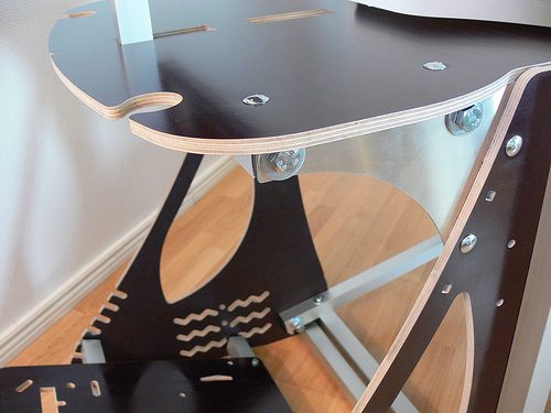
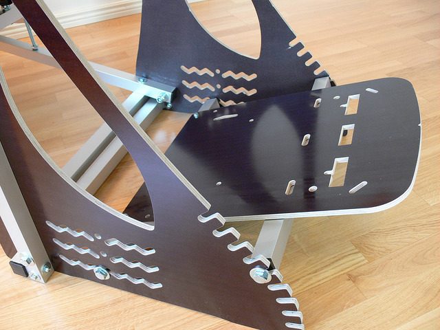
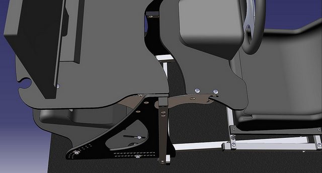
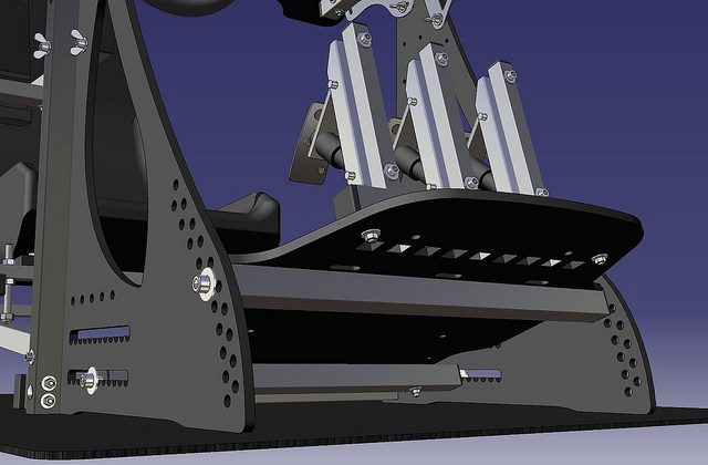
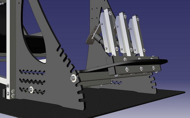
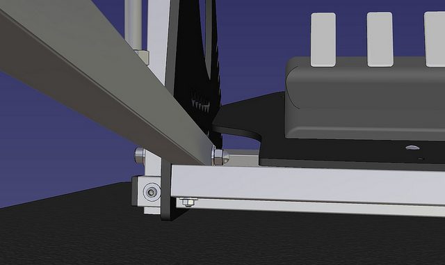
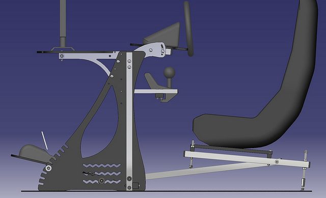
Played around with the inverted pedals, and changed the design a little. More stable and stepless position adjustment possible. Also changed the side ply cut for less openings (cheaper to watercut) and for less fragile shape:
blog entry for the day:
Weight without bolts & nuts etc. is 9,9kg calculated from the 3D model. (includes plywoods, steel parts & aluminium tubes)
...slowly nearing the phase of first cost enquirys for the precut parts (plys & steel sheets)
EDIT,
Played around with the inverted pedals, and changed the design a little. More stable and stepless position adjustment possible. Also changed the side ply cut for less openings (cheaper to watercut) and for less fragile shape:
Pic 1
Pic 2
Pic 3

Pic 2
Pic 3
Last edited:
Timppaq
Premium
- 5,137
- Helsinki
- GTP_Timppaq
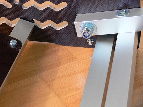
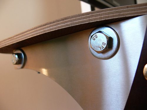
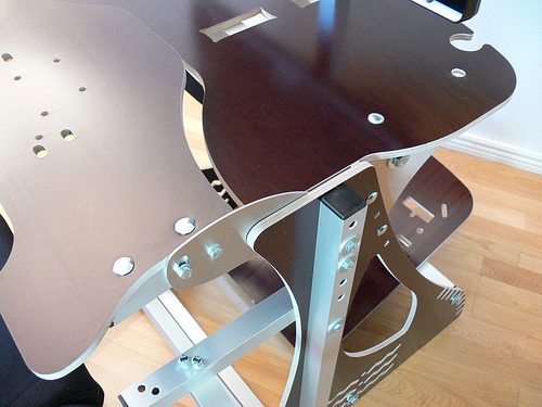
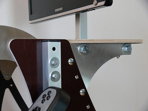
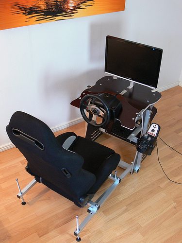
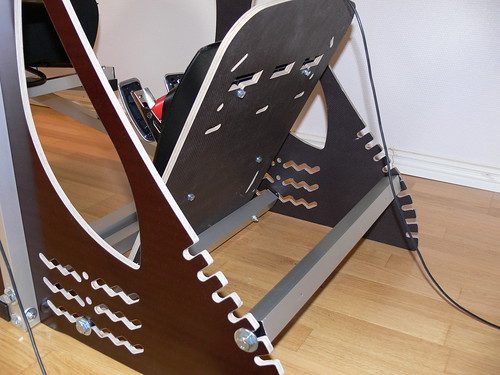
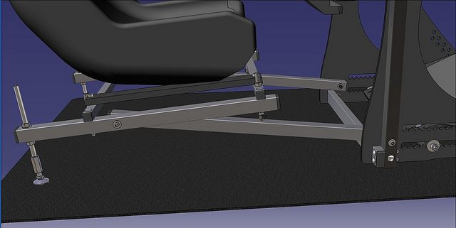
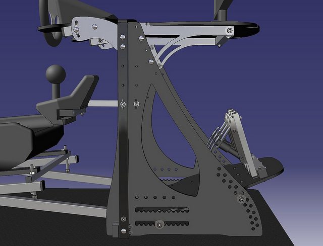
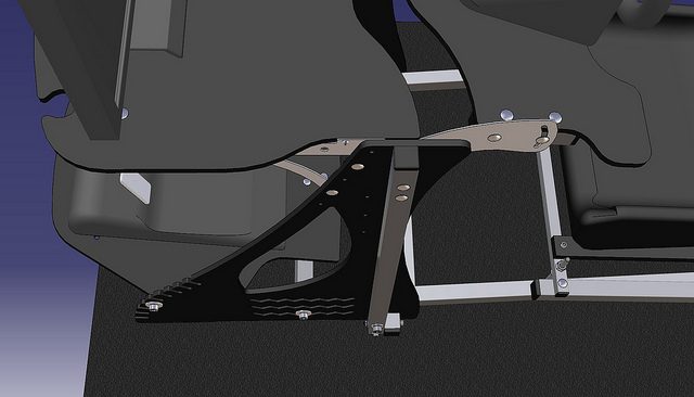
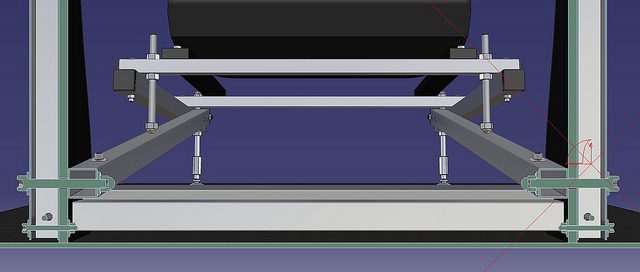
Changed the solution for the most crucial part of the rig, the corner joint:
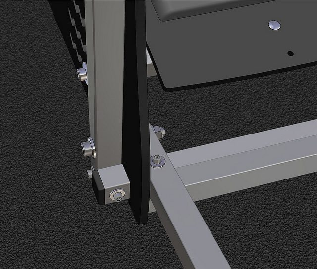
Had my doubts of having double bolts there (check previously posted pics).. instead of depending on tightening the double bolts very tight added one more cross bar under the angled longnitudinal bars on seat section:
My understanding of this says that I should still have really stiff joint in cross direction while still maintaining the agle/height adjustment for the seat. There shouldn't be any chance for the stand to rock sideways as long as the bolts are properly tightened, especially the bigger (M10) bolts. Rocking sideways would require the corner joint's 90deg. agle to change and that shouldn't be possible now.
The problem with the double bolts was that it would've required really accurate drilling (to get the 90 deg. angle) of the two side by side holes (also with tight fit holes) and I thought this to be little bit too demanding to be done in home environment. Also the needed tightening force could've possibly deformed the alu tubing, and preventing that would've been little complicated even though possible. Even if there's now one more aluminium tube I see the benefits outweighting the cost & extra work of the added part.
Still, I do have a plan B for adding 100% certain rigidness for the joint if this still fails - you never truly know before you've tried it in rl. After I've ordered the parts (will be costly) there can't be any chance for the rig not to work as I've planned!

********************************
I've tried to continuously lower the part count, and I think I'm nearing the minimum I can think of - with still having all the features (mainly adjustability) that I want.
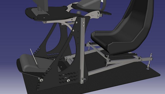
Here's the subassemblies just for fun:


Put together:
Had my doubts of having double bolts there (check previously posted pics).. instead of depending on tightening the double bolts very tight added one more cross bar under the angled longnitudinal bars on seat section:
My understanding of this says that I should still have really stiff joint in cross direction while still maintaining the agle/height adjustment for the seat. There shouldn't be any chance for the stand to rock sideways as long as the bolts are properly tightened, especially the bigger (M10) bolts. Rocking sideways would require the corner joint's 90deg. agle to change and that shouldn't be possible now.
The problem with the double bolts was that it would've required really accurate drilling (to get the 90 deg. angle) of the two side by side holes (also with tight fit holes) and I thought this to be little bit too demanding to be done in home environment. Also the needed tightening force could've possibly deformed the alu tubing, and preventing that would've been little complicated even though possible. Even if there's now one more aluminium tube I see the benefits outweighting the cost & extra work of the added part.
Still, I do have a plan B for adding 100% certain rigidness for the joint if this still fails - you never truly know before you've tried it in rl. After I've ordered the parts (will be costly) there can't be any chance for the rig not to work as I've planned!
********************************
I've tried to continuously lower the part count, and I think I'm nearing the minimum I can think of - with still having all the features (mainly adjustability) that I want.
Here's the subassemblies just for fun:
Put together:
Last edited:
Timppaq
Premium
- 5,137
- Helsinki
- GTP_Timppaq
Very nice!
Thanks! And thanks for the reply too, seems a bit silent on this part of the forum these days!
- 127

- The Netherlands
- Bigbembem1994
it may is a stupid question, but is it going to be for yourself only or for production?💡
I think you really should put it in production (like V1). It's an amazing seat.
and if you're going to put it in production, are you going to make a holder for the fanatec shifters?
I'm really interested")
I think you really should put it in production (like V1). It's an amazing seat.
and if you're going to put it in production, are you going to make a holder for the fanatec shifters?
I'm really interested
Timppaq
Premium
- 5,137
- Helsinki
- GTP_Timppaq
I will order 10 (about - maybe 20 max. - we'll see) sets of the parts (plywoods & steel sheets) and of course will try to sell the rest that I don't need 👍 Ordering just one or two sets would almost be as expensive as 10, so surely will order more. So if you want one, it's possible.
What shifter do you mean precisely? I will make it compatible with the G series, TM wheels & the Fanatec lineup.. just for now I haven't been yet in the phase to check if all is compatible, but of course it will be in the end.
The 'concept' if you wish to call it that, is that I just send the parts that you can't do yourself and rest you do yourself. It's kind of half DIY, and it might not be for all but cutting alu tubes to lenght and drilling some holes to those shouldn't actually be that hard so it should be doable if you have the will.. 👍
With the 'V1', I have also additionally made the alu tubes for some customers (as they hoped so, and they were in Finland), but since then I have moved and I don't have all the tools & space to do that anymore. It's about 50 holes this time (if I counted right) that is needed to be drilled (to the alu tubes) and adding to that cutting the tubes to lenght should take about one night to complete. I honestly think it's fairly reasonable for basically a 'DIY' rig.
fyi, the ply's will be water cut and the steel sheets laser cut, just like last time.
edit,
Thanks for the compliment!
What shifter do you mean precisely? I will make it compatible with the G series, TM wheels & the Fanatec lineup.. just for now I haven't been yet in the phase to check if all is compatible, but of course it will be in the end.
The 'concept' if you wish to call it that, is that I just send the parts that you can't do yourself and rest you do yourself. It's kind of half DIY, and it might not be for all but cutting alu tubes to lenght and drilling some holes to those shouldn't actually be that hard so it should be doable if you have the will.. 👍
With the 'V1', I have also additionally made the alu tubes for some customers (as they hoped so, and they were in Finland), but since then I have moved and I don't have all the tools & space to do that anymore. It's about 50 holes this time (if I counted right) that is needed to be drilled (to the alu tubes) and adding to that cutting the tubes to lenght should take about one night to complete. I honestly think it's fairly reasonable for basically a 'DIY' rig.
fyi, the ply's will be water cut and the steel sheets laser cut, just like last time.
edit,
It's an amazing seat.
Thanks for the compliment!
Last edited:
- 15,854

- QLD, Australia
- Small_Fryz
Wow.
Top shelf Timo, just like your driving
Once I get a pay rise... I know what's on my list!
Top shelf Timo, just like your driving
Once I get a pay rise... I know what's on my list!
- 963

- Toronto, Canada
- times_fade
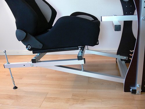
100% respect for your design, you should benefit from the new shaped side ply quite a lot.
I don't quite understand the seat frame portion, will you have small notches for the front adjusting bolt to klick into, or is it going to rest on the bare alu tube? I think this could be a lot of pressure on a single point after a while and start bending. I know a lot of the weight will go down into the rear support, but over time it might kink the tubes. I guess to solve that you could add a U-shaped bracket which disperses the weight over a couple of cm.
I don't quite understand the seat frame portion, will you have small notches for the front adjusting bolt to klick into, or is it going to rest on the bare alu tube? I think this could be a lot of pressure on a single point after a while and start bending. I know a lot of the weight will go down into the rear support, but over time it might kink the tubes. I guess to solve that you could add a U-shaped bracket which disperses the weight over a couple of cm.
Timppaq
Premium
- 5,137
- Helsinki
- GTP_Timppaq
100% respect for your design, you should benefit from the new shaped side ply quite a lot.
Thanks. I'm quite sure it would've been ok even without the change, but there's really no downside doing it this way either - if something, it can only be for better. (the base plysheet needed is still the same size)
I don't quite understand the seat frame portion, will you have small notches for the front adjusting bolt to klick into, or is it going to rest on the bare alu tube? I think this could be a lot of pressure on a single point after a while and start bending. I know a lot of the weight will go down into the rear support, but over time it might kink the tubes. I guess to solve that you could add a U-shaped bracket which disperses the weight over a couple of cm.
Thanks for the notice, I will keep this in mind and if needed will figure some solution. I'm certain the tube as a whole won't bend but the point load of the adjustment bar could possibly under a heavy person cause a slight dent to the upper face. Maybe just a basic (thick) washer etc. under the bar tip could do enough to spread the load. 👍

Energizerrr
(Banned)
- 1,115
Amazing work, just wow.

Timppaq
Premium
- 5,137
- Helsinki
- GTP_Timppaq
Anybody has any experience with joining aluminium (/metal) parts with epoxy (or with any other kind) glue? My Plan C is to secure the main 90deg. joint with glue (really shouldn't be needed, but actually could be fun to try the results - this might open whole new possibilities for DIY'ers), if there is no other way to ensure 100% rigidity.
Something like this is what I had in mind, but any other proposals are welcomed 👍

http://www.loctite.co.uk/cps/rde/xc...redDotUID=productfinder&redDotUID=1000000IC0F
edit,
Something like this is what I had in mind, but any other proposals are welcomed 👍
http://www.loctite.co.uk/cps/rde/xc...redDotUID=productfinder&redDotUID=1000000IC0F
edit,
Last edited: