- 1,833

- United Kingdom
- WarriusZero
It's a mini batmobile? ")
Kind of, except much lighter and rotary powered.It's a mini batmobile?
But they do own the rights to it if I remember correctly.Even though they didn't invent or were the first to put it in a car
Kei just annoys the 🤬 out of me, I hate that name lmao, but Ignore me as I'm am a Ps3 peasantWho said anything about 'Mazda'?... Maybe i should have said 'Dynakinectic powered' or something. The engine would still be of the rotary kind. Besides, iv'e changed the name to 'Kei Class Roto Fighter' or just 'Roto Fighter' for short'.
I own a PS3 too.I'm am a Ps3 peasant
Well then..... We both can enjoy our peasantsyI own a PS3 too.
I'm am a Ps3 peasant
Awsm thing is I ain't getting a Ps4 for a whilePretty much all of us in this forum have PS3's
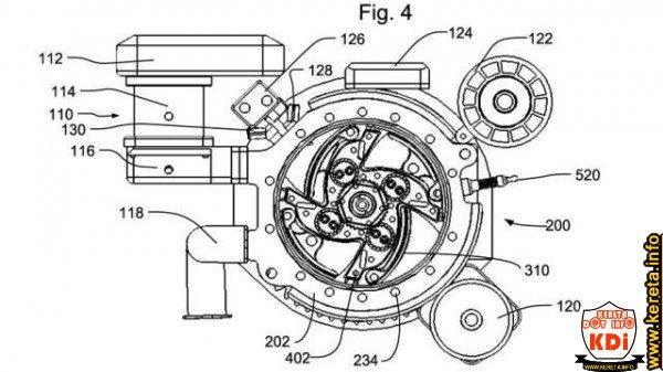


That Gtp logo on da side thoughHere's the kind of engine i was thinking.
GoTek Dynakinetic engine:
Imagine a bank of these:
Slight update of the 'Kei Class Roto Fighter'
Added some shutlines and rear lights:
I gave the fenders a bit of character, going from a round shape to a more angular, like the shoulder blades of a crouching tiger. The dragon (engine) is hidden underneath the air intake in the rear.
View attachment 299963
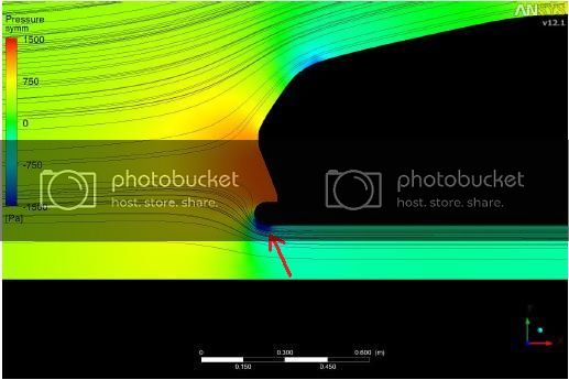
Can you suggest some possible solutions to fix the aero issues? 👍 I'm thinking a wing and maybe some canards, though i'm guessing that won't be enough, (i have little to no grasp of effective aerodynamics).While it looks good I think it has a lift problem. Nothing on the upper surface is pushing it down and there is a lot pulling it off the ground. The really sharp transition from the front fascia to wheelwell will produce a lot of separation and a large drag area.
The angular wheelwell design could be a problem too, though they also might produce a slight amount of downforce. It wouldn't be anything to celebrate about though. The rear fascia has no separation edge anywhere which could lead to massive drag
While it looks good I think it has a lift problem. Nothing on the upper surface is pushing it down and there is a lot pulling it off the ground. The really sharp transition from the front fascia to wheelwell will produce a lot of separation and a large drag area.
The angular wheelwell design could be a problem too, though they also might produce a slight amount of downforce. It wouldn't be anything to celebrate about though. The rear fascia has no separation edge anywhere which could lead to massive drag
Apply for an auto desk student license (needed or not) and get theirs for free.There's low pressure under the car though so I don't think lift will be a problem. Drag might be an issue but it's hard to tell without a wind tunnel. I've been looking for some free wind tunnel software but I didn't find anything yet.
While it looks good I think it has a lift problem. Nothing on the upper surface is pushing it down and there is a lot pulling it off the ground. The really sharp transition from the front fascia to wheelwell will produce a lot of separation and a large drag area.
The rear fascia has no separation edge anywhere which could lead to massive drag
I tried to make Nessy's Kei Class Roto Fighter a little more aero.
View attachment 302738
-Added vents on the front end, to reduce lift.
-Broadened the front fascia in front of the front tires, included a "reverse mudflap" to block the tire a bit more.
-Reduced the size and scale of the side vents. I think having a flat side for the air to reattach to after the front tires is good.
-Added a rear skirt over the rear wheels to compliment the change above.
-Added a rear wing for downforce and clean separation.
 .... Not bad
Can you suggest some possible solutions to fix the aero issues? 👍 I'm thinking a wing and maybe some canards, though i'm guessing that won't be enough, (i have little to no grasp of effective aerodynamics).
There's low pressure under the car though so I don't think lift will be a problem. Drag might be an issue but it's hard to tell without a wind tunnel. I've been looking for some free wind tunnel software but I didn't find anything yet.
I tried to make Nessy's Kei Class Roto Fighter a little more aero.
View attachment 302738
-Added vents on the front end, to reduce lift.
-Broadened the front fascia in front of the front tires, included a "reverse mudflap" to block the tire a bit more.
-Reduced the size and scale of the side vents. I think having a flat side for the air to reattach to after the front tires is good.
-Added a rear skirt over the rear wheels to compliment the change above.
-Added a rear wing for downforce and clean separation.
 Also, would the movable vanes have any affect if they moved when turning (differently on each side, respective of what direction the cars turning). I can appreciate we need actual aero software, but it would be nice to know if we're in the right ballpark. 👍

Added some shutlines and rear lights:
@Exorcet
Thanks for shedding more light on the subject. And thanks @grannyshifter for adding to the design. With regards to the old design, here's a really quick sketch to show some of the hidden curves under the bodywork, (not the chassis though). Would the front not work very well? (aero dynamically speaking).
(Drawing isn't exact and i know i haven't really translated it well on the original sketch i shared, but this is kind of how i'd thought it'd go) :
@Exorcet if they direct more air under the car won't this increase the pressure under the car and cause lift. I would have thought ways of eliminating/removing or extracting air from the undertray would be better with venturi's to create downforce.
This kind of ground effect is easily illustrated by taking a tarpaulin out on a windy day and holding it close to the ground: it can be observed that when close enough to the ground the tarp will be drawn towards the ground. This is due to Bernoulli's principle; as the tarp gets closer to the ground, the cross sectional area available for the air passing between it and the ground shrinks. This causes the air to accelerate and as a result pressure under the tarp drops while the pressure on top is unaffected, and together this results in a net downward force. The same principles apply to cars.
I agree that to create a ground effect the air speed needs to increase, but from my understanding this is more about reducing the cross sectional area that the air is passing through like lowering the car to increase the air speed, not increase the amount of air being forced under it. Here's an explanation I found.