Cheap PC build guide

  • Thread starter Thread starter Nacho Libre
  • 4 comments
  • 1,348 views
Messages
3,839
Mexico
Mexico
Hi all. Since I'm building another gaming PC (this one is for a friend's kid) i decided to document and share the experience, in the hope it's useful. I realize there is a ton of PC building tutorials out there, and you should watch as many as possible if you are looking into PC gaming. Even if you decide to buy a prebuilt PC, it's good to be knowledgeable about the whole process, from picking the components to fit your budget and meet your performance targets (a game into itself!) to putting it together and making it work.

In this first part, I will cover the motherboard (a.k.a. MOBO), the CPU (Central Processing Unit) and fan, together with the RAM memory, the tools you need, some general precautions and tips, including the rationale for picking the parts vs. the allocated budget and the performance goals.

Now, the budget was set by my friend at about US$680, plus a reasonable assembly fee that I will not disclose.

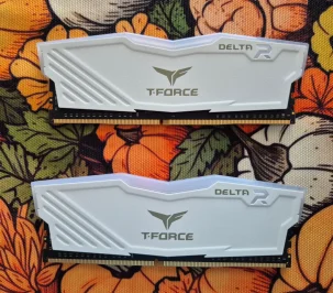
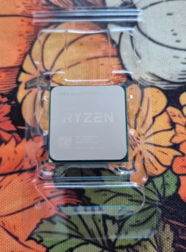
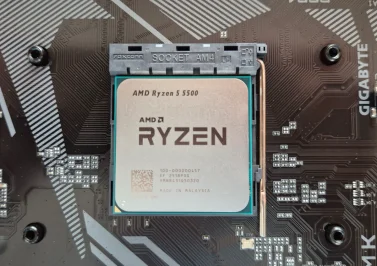
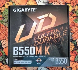
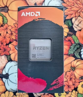
So, my first choice was the CPU/MOBO combo, and I opted for a Ryzen 5 5500 to go with a B550 Gigabyte motherboard. Since this supports DDR4 RAM memory, I went for 16 GB (2x8 GB modules) of T-Force Delta R sticks. I have worked with Gigabyte motherboards and T-Force memory, so I'm comfortable with them. This is my first Ryzen build after using Intel in my personal PC.

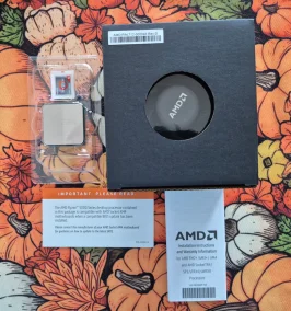
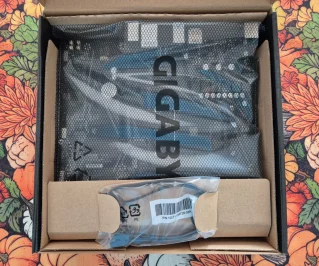
These are the parts in question (pardon the background, as I'm working in the dinner table and the tablecloth is themed for Autumn):
20250915_141645.webp20250915_142449.webp20250915_144745.webp

Tomorrow, I'll illustrate the assembly of these components. Cheers!
 
Last edited:
Part 1: Motherboard/CPU assembly.

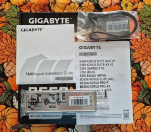
It's important to always check that the boxes containing your components arrive in good shape, with no signs of having been opened, and that all parts/manuals/warranties are accounted for.

20250915_141705.webp20250915_141916.webp20250915_141933.webp

As you can see, the MOBO comes wrapped in an anti-static bag, and comes with an I/O shield that fits in the case, a SATA cable (for a storage unit that uses that connection), and a quick installation guide that you should always read.

20250915_142346 (1).webp

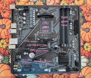
Out of the bag, I placed the motherboard over its carboard box. This gives you a stable, pliable, and static-free surface to work, as you push the RAM sticks into place, and screw the fan over the CPU.

I marked the main parts we are going to use in this step. If you look closely, you will see that the motherboard is full of useful labels to guide you. And the little black square on the bottom left corner is the actual B550 chipset that controls the MOBO: Don't touch, and don't bother.

20250915_142816 (1).webp

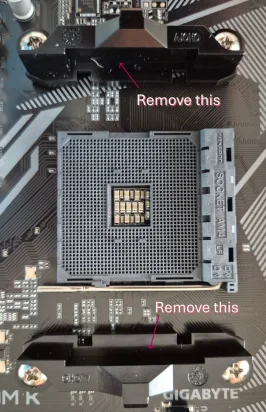
As we look closer, above and below the CPU socket (or seat) there is a couple of brackets that you will need to remove in order to fit the CPU's cooling fan. Use a regular Phillips screwdriver (star-shaped head) to unscrew by applying just the necessary force. Put the brackets and screws back in the fan's box.

20250915_142955 (1).webp

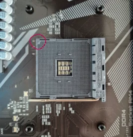
After you remove the brackets, you'll notice four stands where the fan will be screwed over the CPU. Notice the little arrow in the corner. This is an important guide to correctly place the CPU.

20250915_143017.webp20250915_143041.webp

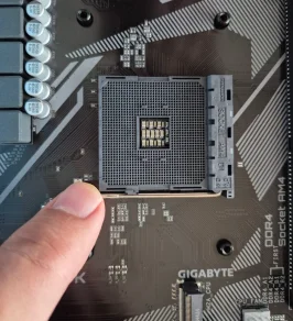
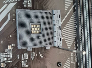
Now gently, pull the lever out and up as shown. Unlike Intel's chips there isn't much pressure, so it doesn't "snap".

20250915_142612.webp20250915_142657.webp

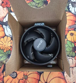
Now you can unbox the CPU, which for this model also contains a stock fan that we will use. Carefully remove the CPU from its wrapper and hold it like I do in the next picture. Warning: It is deceptively heavy.

20250915_143136 (1).webp

Here you see the arrow that needs to be aligned with the one in the socket.

20250915_143112.webp

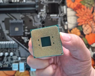
On the backside there are the connecting pins that go into the socket. DO NOT TOUCH THEM AND DO NOT BEND THEM.

20250915_143206.webp20250915_143233.webp

Now, breath, relax and gently place the CPU on its seat by making sure the arrows are aligned. DO NOT PRESS THE CHIP INTO PLACE. Then pull down the lever under that little side tab and see it is not loose. This locks the chip into place.

Coming up: Fan and RAM installation.
 
Last edited:
Part 2: Let's install the fan!

20250915_143329.webp
20250915_143401 (1).webp

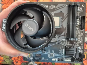
Carefully unbox the fan included with the CPU and turn it upside down. The central metal area is evenly covered with thermal paste. While many builders prefer to remove it and use a brand thermal paste (or thermal pads), I don't recommend it if you are doing a first build. It works just fine, just don't touch it.

20250915_143510.webp

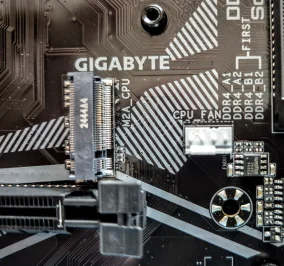
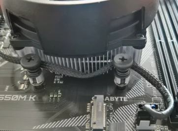
Check where the fan will connect. In this case, to a four-pin connection located down of the bottom right screw hole for the fan, and between the M.2 slot (left), the first slot for the RAM stick (right), and a screw hole for the motherboard that looks like an asterisk.

20250915_143642.webp

Now carefully place the fan over the screw holes with the AMD tab pointing to the CPU.

20250915_143723.webp

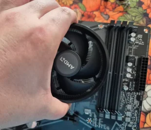
As you can see, you will need your Philips screwdriver. Just hold the top of the fan with one hand and screw in a cross-pattern with the other. Don't force the screws if you feel they are not going down, just wiggle the fan a bit to align the screws to the holes, by applying even force in all sides.

As a side note, this is easier than the stock Intel's fan where you have to drive 4 pins through the motherboard and then turn and lock them into place.

20250915_143947.webp20250915_144008.webp

Anyways, now that you screwed the fan, check by holding the top of the fan and raising the motherboard just a couple of inches (or cm). You will need to do this later when you put the motherboard into the case.

20250915_144058.webp

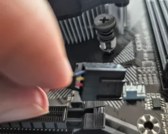
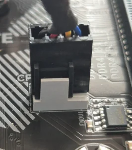
Now hold the connector and see those tabs.

20250915_144305.webp

To plug the fan connector, see that the bottom metal tab aligns with the plastic tabs and push. If it feels too tight, with your fingernail pull the metallic tab slightly towards you, and the connector will slide into place.

20250915_144359.webp20250915_144513.webp

Now for some basic cable management, coil the cable like this, and your fan installation is done.
 
Part 3: RAM installation.

20250915_144745.webp

Get your RAM sticks out, for gaming a capacity of 16 to 32 GB is the usual (for 1080p gaming 16 is fine). Do check that the type/frequency of your sticks is supported by your CPU/motherboard.

20250915_144758.webp

So, where the sticks go? The motherboard makes it easy by identifying the 2nd and 4th RAM channels in gray. They are also labeled in the MOBO itself.

20250915_144822.webp

Open these locks at the top and bottom of the RAM channels.

20250915_144859.webp

Now, to know in which direction they go, look at this side with the label. This faces the CPU/fan installation. Also note the small gap underneath.

20250915_144920.webp

You have to align that gap with the slots in the RAM channel.

20250915_145005.webp

Now, this is why working over the MOBO's box is recommended, because you will need to exert even pressure over the RAM stick when pushing downward until the locks click.

20250915_145128.webp

Notice the position of the lock tabs. You can wiggle the stick a bit to see it's fully locked in place, but if you feel unsure, unlock and repeat.

20250915_145238.webp

Now you have installed the RAM sticks in the dual channel configuration that is optimum for performance.

In short, dual-channel RAM is a memory architecture that allows two RAM modules to communicate with the CPU simultaneously, effectively doubling the data transfer bandwidth compared to single-channel configurations. (Source: Copilot)

20250915_145303.webp

Your CPU/Fan/RAM installation is complete. Since for this build, I will use a SATA SSD, the 2 M.2 slots will not be used now, but they can be used later for expanding storage. Next we will be working with the case, PSU, and all the cabling involved...
 
Part 4: Case, cables and storage installation.

I assume you have seen gaming CPU cases before. They are just like regular cases except they have a tempered glass panel on one side, and a metal panel on the opposite side. After unboxing the case, we will remove said panels by unscrewing their affixing bolts (4 for the glass panel and 2 for the metal panel), and we will set them aside. Be extra careful with the glass panel and keep track of the all the bolts.

20250916_074248.webp

We will call this the backside, where the main cabling goes. The black cables are for the front (or top panel or sometimes side panel) switches and connectors, and the white cables are for the preinstalled fans (convenient!). The enclosure below is for the power supply unit (or PSU, hereafter) and a little cage for either old-style HDD storage or SSD SATA drives.

20250916_074356.webp


Now I'm holding the hydra's head, notice that all connectors are labeled for easy identification.

20250916_074433.webp

Those cables correspond to these connectors and switches in this top panel. From left to right, the 3.0/3.1 USB, the 2.0 USB (2), jacks for the headphones and microphone, the reset button, two LED lights for power on/off and disk activity (relics at this point, really), and the Power ON/OFF button.

20250916_074414.webp

Now notice these screw holes on the backside. There are for bolting a SSD SATA drive there, and we will use them for this build.

20250916_074740.webp20250916_074908.webp20250916_074948.webp

This is our selected SATA SSD with a capacity of 1 TB. Notice the screw holes on the back, but... there are no screws in the box!

20250916_074547.webp

Not to worry, your case will include a bag with all the bolts required and sometimes those plastic straps for cable management.

20250916_075513.webp

Open the bag and organize your bolts; some are for bolting the motherboard, and others are for the PSU and storage drives (if any).

20250916_112541.webp

You got to LOVE magnetic screwdrivers!

20250916_081141.webp
20250916_080937.webp

Anyways, it's pretty straight forward. Hold the drive on one side like this and bolt from the other side. It's upside down because it's two connectors for power and data transfer have to face to the left, as you can see here.

20250916_122548.webp

To the left is the power connector and to the right is the data transfer connector, but we will not connect them yet.

20250916_081224.webp

This is why you remove both panels, because for the next steps you will be manipulating the case a lot and it will have to lay over one side or the other.
 
Last edited:

Latest Posts

Back