Sounds like the FETs need replacing, if it can turn one way but not the other it's likely that the H-bridge driver is incomplete. I'll look through my notes later and give you some possible part numbers. I hope you or someone you know is competent at SMD soldering, though.
And no, you can't replace the motors with brushless ones (as far as I know, at least) because they work differently.
Edit: so here's the info I've got...
The G27 uses a Johnson HC685LG-011 brushed DC motor, driven by one IRF 7342 dual P-channel MOSFET and one IRF 7103 dual N-channel MOSFET, in an older version of the wheel (newer version use different components with the same spec, I'm fairly sure I wrote the names down somewhere but I can't find them right now.)
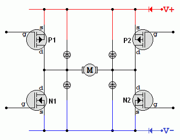
These four FETs are arranged in an H-bridge, as I mentioned, which looks like this:
Except instead of four diodes there's just one big TVS diode across the motor (I think, I'm kind of going from memory, but there are markings on the G27's PCB for additional diodes - it may have been cheaper to use one big diode, not necessarily better).
The way this works is one pair of P and N-channel FETs will turn the motor one way, the other pair will turn it the other way. If it can only turn one way, that suggests one or both of the FETs responsible for turning the wheel in the direction it won't turn are blown. It could also be a short circuit at some point along the signal path from the microcontroller to the FETs or the microcontroller is malfunctioning and the pin that sends the signal to turn the wheel to the right is damaged, blown or whatever. You could also test the optical encoder to rule that out as the cause, you could hook it up to a 5V supply then test the output pins with an oscilloscope to see the rising and falling edges as you turn the encoder both ways.
Hope that helps!
Edit again:
Or models RS555 for Upgrade?
I don't think so, no. I can't find a good datasheet for it but anything with a higher stall torque than the OEM motor will blow the FETs the first time you stall the motor by fighting the FFB. They do have a safety margin but it's not huge, from what I can remember, and the only cooling they have is a thermal relief pad on the bottom of the IC - that's why the part of the PCB they're on is uncoated copper because the solder mask hinders thermal transfer.
Also you'd need one of the replacement motors to have two shafts so the encoder has somewhere to go.


