- 1,092

- Pierrefonds (Montreal), QC
- pilmat
- pilmat
Being gifted/cursed with long legs, I often suffer from low knee clearance in seated positions (cars, planes, sim rigs, etc.). When I brought home my shinny new G27 a few months ago, I immediately smacked my knee on the table clamp. Flipping the base over, it is immediately apparent that Logitech intend you to use the clamps even when mounting off the rear bolt mounts on a rig. Not good enough!
I pulled the base apart to see what was inside. I had a fix within a few minutes: mount the base with 2 of the screws used to hold the main steel frame inside the base. The biggest pain was removing the clamps! The wheel needs to be removed and the base cover removed to get access...
This mod is only good if you are mounting the G27 "permanently" (i.e. on a rig), as the clamps are removed and screws are necessary.
Here is what the mod looks like, as I'm doing it for a friend's new Human Racing GT Chassis install. At 6 foot, I'm not extraordinary, so others must suffer from the same affliction (my friend SGPracing, for one). Here is is what the issue was on my old rig, here it's not bad but the pedals were a bit too far away here too:

See the photo sequence in full size here. There is descriptions there too.
G27 Table Clamps

These are the buggers.
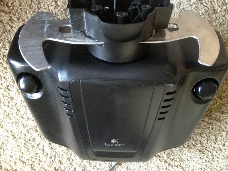
Underside (stock)

This is the underside of the G27. The crooked row of black Philips screws is used to attach the internal steel frame to the base. We will use the middle two to replace the clamps.
Chassis screws used for front screw mounting

Here the screws are removed. They are M4 and need to be at least 16 mm plus the thickness of your mounting plate.
Screw instalation

This is what the mounting will look like. This is the plate from the Human Racing GT Chassis. The insanely long M4 screws are for demonstration purposes
Remove the wheel
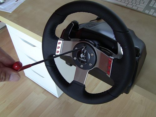
Now the painful part: removing the clamps. Start by removing the wheel. Note that when the last screw is removed, it will want to come off, but the button wire harnesses are still attached. Don't pull too hard!
Remove the wheel PCB screws

(sorry about the shaky cameraman)
Now take off the two little Philips screws that hold the wheel PCB on. You will also need to take off the shift light "periscope". Again, the PCB is still wired to the base, don't pull too hard.
Disconnect the wheel PCB

Here you see the PCB to base wiring attachment. Just pull that plug off (carefully).
Remove the wheel hub

Now take off the 3 center screws. Not the outer ones, they only hold the paddles on.
Wheel hub removed
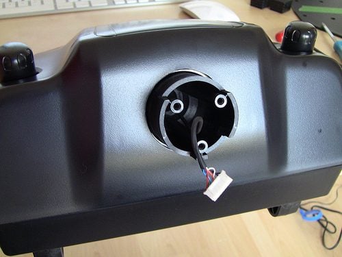
The hub removed and ready to remove the base cover.
Remove all the OUTER base screws
Remove the outer 8 screws, not the two other chassis screws or the cord winder.
Clamps as installed

This is what the clamps look like inside. Just a threaded rod in a plastic U-clamp.
Clamp and rod removed.

Just unthread the rod and push the clamp out the bottom. Now put it back together")
The holes left from the clamps

Here is the base back together (you did remember the shift light periscope? ) and the gaping holes left by the clamps. I put a piece of clear packing tape over them for dust. But maybe somebody has a creative use
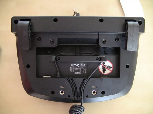
The base drilling pattern

This is the drill pattern: the holes are off set 108mm from the back mounting holes (centre to centre) and are 107mm apart (53.5mm to the centre line on the photo).
Finished

And a nice, elegant installation (minus the two holes on the base top...)
If I missed anything, please ask
I pulled the base apart to see what was inside. I had a fix within a few minutes: mount the base with 2 of the screws used to hold the main steel frame inside the base. The biggest pain was removing the clamps! The wheel needs to be removed and the base cover removed to get access...
This mod is only good if you are mounting the G27 "permanently" (i.e. on a rig), as the clamps are removed and screws are necessary.
Here is what the mod looks like, as I'm doing it for a friend's new Human Racing GT Chassis install. At 6 foot, I'm not extraordinary, so others must suffer from the same affliction (my friend SGPracing, for one). Here is is what the issue was on my old rig, here it's not bad but the pedals were a bit too far away here too:
See the photo sequence in full size here. There is descriptions there too.
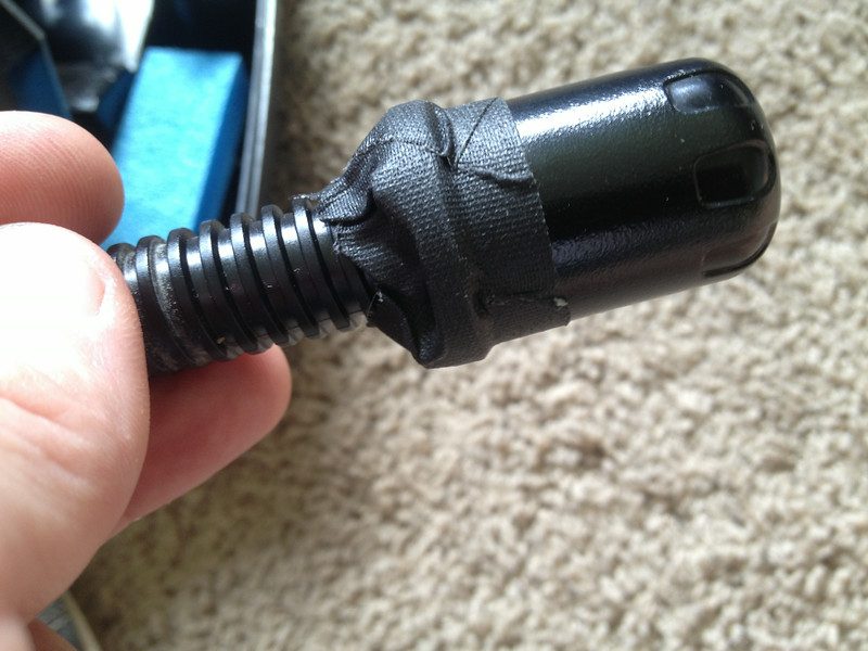
G27 Table Clamps
These are the buggers.
Underside (stock)
This is the underside of the G27. The crooked row of black Philips screws is used to attach the internal steel frame to the base. We will use the middle two to replace the clamps.
Chassis screws used for front screw mounting
Here the screws are removed. They are M4 and need to be at least 16 mm plus the thickness of your mounting plate.
Screw instalation
This is what the mounting will look like. This is the plate from the Human Racing GT Chassis. The insanely long M4 screws are for demonstration purposes
Remove the wheel
Now the painful part: removing the clamps. Start by removing the wheel. Note that when the last screw is removed, it will want to come off, but the button wire harnesses are still attached. Don't pull too hard!
Remove the wheel PCB screws
(sorry about the shaky cameraman)
Now take off the two little Philips screws that hold the wheel PCB on. You will also need to take off the shift light "periscope". Again, the PCB is still wired to the base, don't pull too hard.
Disconnect the wheel PCB
Here you see the PCB to base wiring attachment. Just pull that plug off (carefully).
Remove the wheel hub
Now take off the 3 center screws. Not the outer ones, they only hold the paddles on.
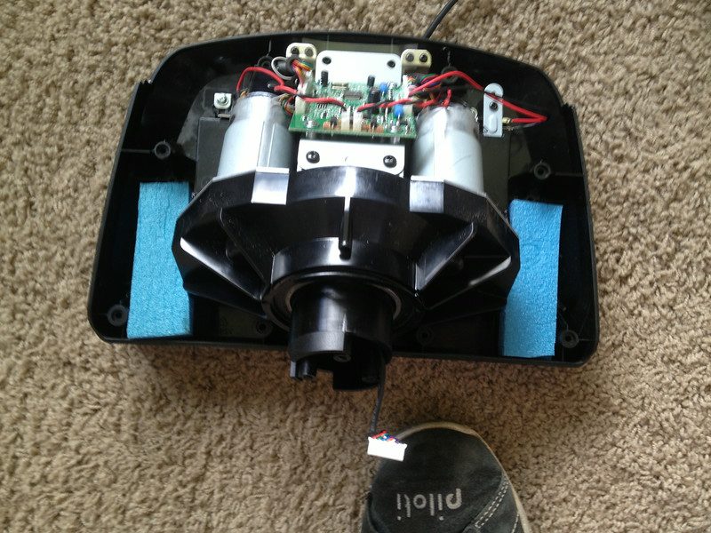
Wheel hub removed
The hub removed and ready to remove the base cover.
Remove all the OUTER base screws
Remove the outer 8 screws, not the two other chassis screws or the cord winder.
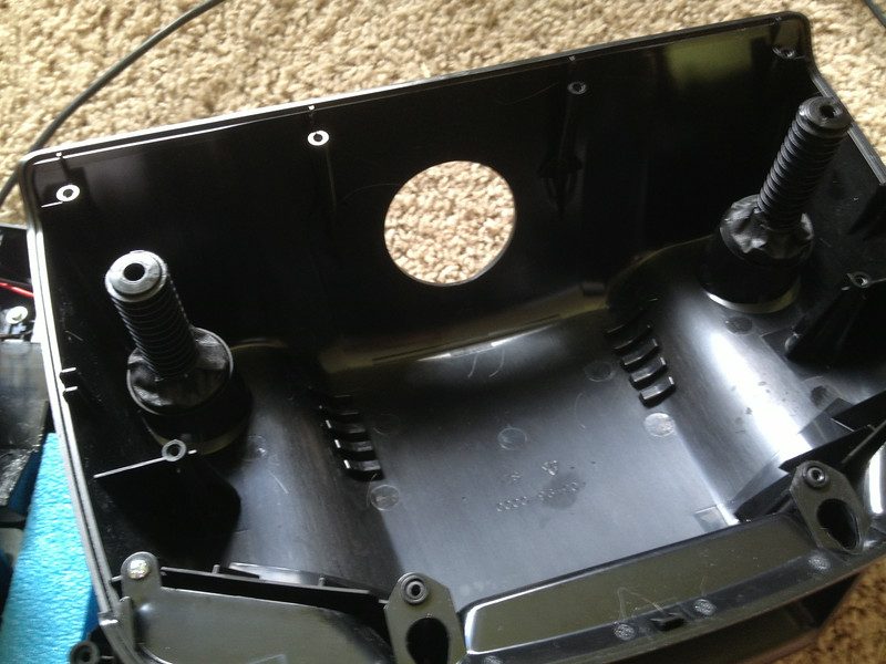
Clamps as installed
This is what the clamps look like inside. Just a threaded rod in a plastic U-clamp.
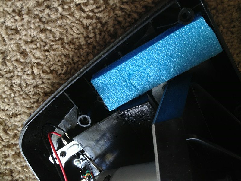
Clamp and rod removed.
Just unthread the rod and push the clamp out the bottom. Now put it back together
The holes left from the clamps
Here is the base back together (you did remember the shift light periscope?
) and the gaping holes left by the clamps. I put a piece of clear packing tape over them for dust. But maybe somebody has a creative use The base drilling pattern
This is the drill pattern: the holes are off set 108mm from the back mounting holes (centre to centre) and are 107mm apart (53.5mm to the centre line on the photo).
Finished
And a nice, elegant installation (minus the two holes on the base top...)
If I missed anything, please ask
 ).
).")