Logitech DFGT temp problem

  • Thread starter simracer5
  • 13 comments
  • 3,952 views
9
United Kingdom
United Kingdom
Hi

I have seen few threads about the cooling mod on here but my question relate to which fan to get so will cool the motor and PCB down, after checking the temps my motor running at 56C after about 1h racing in project cars also Mosfets on PCB have temp of around 42-46C thats with top case open, so most likely lot hoter with case on now I can get 5v/12v/24v fans to cool this thing down but not sure on best option, how about 24v fan contacted straight to power supply plug? also opened my DC motor to give good clean out and check the brushes soon they will need replacing if possible.

Regards
simracer
 
also opened my DC motor to give good clean out and check the brushes soon they will need replacing if possible.
Try to find brushes from another Johnson motor which are the same as the original ones.

This is electric motor from DFGT with replaced brushes:


Snapshot_20180407.JPG


This is the part of the other Johnson motor:

Snapshot_20180407_1.JPG


I do not recommend the motor from which I took the brushes because it is very expensive,45 euro.
 
Last edited:
Try to find brushes from another Johnson motor which are the same as the original ones.

This is electric motor from DFGT with replaced brushes:


View attachment 728062

This is the part of the other Johnson motor:

View attachment 728063

I do not recommend the motor from which I took the brushes because it is very expensive,45 euro.


Hi thanks do you have the link for this motor you mentioning, 45 Euro is not to bad, looking at the pic you posted with brushes looks like mine are worn about 3/4 so not much left, maybe my wheel will work better with new motor anyway.
 
Hi thanks do you have the link for this motor you mentioning, 45 Euro is not to bad, looking at the pic you posted with brushes looks like mine are worn about 3/4 so not much left, maybe my wheel will work better with new motor anyway.
Here's the motor,but you can not use it because it's too powerful and will burn the wheel.

This looks like a different electric motor.
 
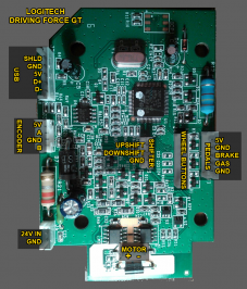
I been having some problems with the wheel, decided to move the motor to other side and by the time I sorted so the pinion would stay on shaft wheel decided it didn't like it and stop working, now everything is working apart logitech can't see the wheel moving at all, inspected the optical encoder wheel, check encoder board, check encoder wires to PCB, then moved to PCB it self, the only think I can see on PCB is C20 & C21 have no resistance of any kind same with P6KE27CA that should be 10K, now this P6KE27CA is responsible for movement of he wheel but I think is only when the power is applied, anyone on here that can help with C20 and C21 is right behind optical encoder plug ???

Otherwise the only option I have is new upgraded wheel

dfgt board.jpg
 
the only think I can see on PCB is C20 & C21 have no resistance of any kind same with P6KE27CA that should be 10K, now this P6KE27CA is responsible for movement of he wheel but I think is only when the power is applied, anyone on here that can help with C20 and C21 is right behind optical encoder plug ???

C20 and C21 are capacitors so they should appear to be open circuits (i.e. practically infinite resistance/impedance), the P6KE27CA is a 27V Zener diode designed to protect against high transient voltages, why do you think it should have a resistance of 10K?

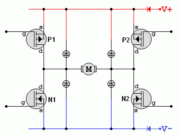
The components that drive the wheel are the two ICs to the left of the motor jumper on the board which are labelled M1 and M2 in the photo, they're MOSFETs that form an H-bridge driver similar to this:

Motor-Driver-H-Bridge.gif

I have see video online mentioning that this should be 10k resistance, maybe I was wrong, managed to get the wheel running now is well, all re calibrated and running but only for 5 min then the might pinion slips again so have to go back to running the wheel as std, question is can I still have the optical encoder mounted on back of motor as it won't go back to original place due to larger hole? asking before I do some more damage?
 
ok just tried to mount the optical encoder on back of motor when the motor is in original location, with the polarity changed as it was original will not work, changed polarity and it works but you turn left wheel showing turning right, I wished I never touched this now
 
but you turn left wheel showing turning right, I wished I never touched this now

That sounds like the encoder is mounted or wired backwards, it has two outputs and if they're the wrong way around it'll read the opposite of what you expect. But I doubt you've got the connectors on the wrong way because then the power and ground would also be wrong so it wouldn't work at all.
 
and it works but you turn left wheel showing turning right, I wished I never touched this now
This is because there is an intermediate gear between the steering wheel shaft and the electric motor,this changes the direction of rotation while at the original position the optical encoder rotates directly from the steering wheel shaft.
 
That sounds like the encoder is mounted or wired backwards, it has two outputs and if they're the wrong way around it'll read the opposite of what you expect. But I doubt you've got the connectors on the wrong way because then the power and ground would also be wrong so it wouldn't work at all.


well you right I had to mount encoder on back of motor now and motor is fitted on left like originally was mounted, but when you oped the wheel from factory encoder was mounted on different shaft, so technically speaking I need to reverse the encode signal left to right and right to left, do you know what wires are which got black/yellow/white/green, I need to change the channel so it should read correctly.
 
Back