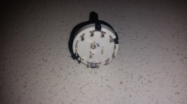
Ah, yeah, as I suspected what you've got is a rotary swich, not a rotary encoder. Sadly, these are completely different devices:
- Rotary switches have a limited number of positions (as you know), a fairly hard 'snap' action when you turn them and a whole load of pins. They're good as selector switches. I've got two next to me as I type this, one for my G27 to switch it between my PC, PS3 and off (disconnected) and another for my headphones to switch them between my PC, PS3, Xbox 360 and then I have a channel spare in case I ever need to add another.
- Rotary encoders can turn infinitely in either direction, they have a gentle 'step' action and only three pins (that is if you have a pretty bog-standard encoder with no push button - they can have more pins). They're good as relative 'up/down' switches, so they're often used in stereos/hi-fis for volume knobs, in microwaves as time setting knobs and other things where you'll want to be able to reset them to zero without requiring the user to manually turn the knob back. Basically, any control that has an 'up/down', 'forward/back', 'left/right' or '+/-' setting can use a rotary encoder instead.
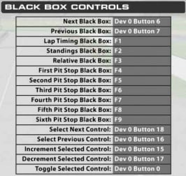
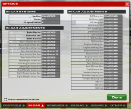
So, long story short, you can't do what you want with what you've got - you need an encoder. I don't know anything about iRacing so I don't quite understand what you mean by "one rotary for various chat channels and the other for position, lap times, difference etc."; does it have a 'previous/next chat channel' input? Could you take screenshots of the key mapping screen(s) so I could get a better understanding, please?
In any case, don't get rid of your rotary switches just yet. You could use what you've got to effectively multiply the encoder you'll eventually buy; instead of having several encoders, you could just have one rotary encoder and one mode selector rotary switch. Your 3P4T (three pole, four throw) switch could replace four rotary encoders with an integrated push switch, provided the device you're connecting them to has that many inputs.
About the three pole, four throw thing: Switches are described as having a certain number of poles and throws, almost always abbreviated to
xP
yT, so in your case you have a 3P4T. The 'throw' bit is easy to explain; it's how many positions a switch has, while the poles is a little harder; it basically describes how many actual electrical switches are inside your switch; if you want one button to create two entirely separate connections at the same time you'd use a switch with two poles. This might help explain it a bit clearer:
The dotted line is used to indicate that the switches are joined together, so when one is switched the other will be too (otherwise it would just look like two separate D or SPST switches above one another). So this should help you visualise what's going on inside your switch, but I know from experience that it's quite tricky to get at first - trust me, you'll learn the difference pretty quickly if you keep ordering SPDT switches when you wanted DPST! This should help make it clearer still:
You can see that pin A will connect to pins 1, 2, 3 or 4 depending on which position the knob is turned to, B connects to 5-8 and C to 9-12. Your switch should have the same markings on it, I've never seen a switch of that type without alphabetical labeling for the inner pins and numerical for the outer.
So, can you post info (links, manuals, even just the name) on the boards you're using to connect your buttons to your PC, please? It might make it clearer as to which rotary encoders would be best for what you want to do. I've used
Bourns ECW1D-B24-BC0024L encoders before and they seem pretty good but I was using them with
a hardware decoder which is a bit complex. It may be that the board you're using is preconfigured to allow you to use encoders with no hassle, I know the Leo Bodnar boards do that.
Edit: I see the 'JC32' you referred to is your controller board, and it supports encoders. That's great, I suggest getting at least one of the encoders I linked above and you should be good to go, wiring it up to the rotary switch to get more functions out of it would be so easy, too.


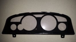
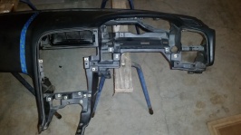
 My jc32 just arrived from SymProjects and I need help with what buttons should be doing what in game. I'm still a rookie at 2.66 Sr from 10 races. I've been practising lots and been away with work for the last 3 weeks. I bought some buttons already 2 rotary encodes with 4 positions on the dial. 10 push momentary buttons and 5 up / down monetary toggle switches. Also I managed to obtain a Nissan skyline R33 dashboard console for 99 cents lol and would like to use the hazard switch for the pit button lol. Later today I'm also picking up the centre console, cluster and gear stick surround today. I'm going to cut the passenger side of the dashboard off to make it all a bit smaller. I have the logitech z906 5.1 system and will mount the volume control unit like a cd player lol.
