GTrr 2.0 - With pictures now! *closed*

  • Thread starter Timppaq
  • 106 comments
  • 20,553 views
Nice looking rig, as there are no dimensions my concern with the screen mount would be the support connection with the top deck and then the ability to adjust screen distance from the user. With a Vesa Mount on say a 24" display it might be a touch far away. Hard to tell but this is just my opinion. Looking forward to seeing this finalised.

Cheers

gsl

p.s. Now I see it on a pc screen and not an iPhone! I'd say the mount would probably work. but I still have concerns on the distance of the screen from the user.
 
Last edited:
Timppaq
Anybody has any experience with joining aluminium (/metal) parts with epoxy (or with any other kind) glue? My Plan C is to secure the main 90deg. joint with glue (really shouldn't be needed, but actually could be fun to try the results - this might open whole new possibilities for DIY'ers), if there is no other way to ensure 100% rigidity.

Something like this is what I had in mind, but any other proposals are welcomed 👍

http://www.loctite.co.uk/cps/rde/xchg/SID-BCD86EB4-9821ACB9/henkel_uke/hs.xsl/fullproduct-list-loctite-4995.htm?iname=Loctite+3423+&countryCode=uke&BU=industrial&parentredDotUID=productfinder&redDotUID=1000000IC0F

edit,

I've never tried Loctite epoxy, I'm sure its high quality like all other Loctite products. However I've used PC-7 epoxy quite extensively and it's never let me down. Still use it to fill the water holes on cylinder head surfaces to seal water from the block deck surfaces completely when you only circulate water in the heads on drag race motors. Cylinder head porters use it quite a bit as well when they want to "move" the runner walls/floor, or change the size of the cross section. Stuff works like a freakin champ on any surface or material...
 
Nice looking rig, as there are no dimensions my concern with the screen mount would be the support connection with the top deck and then the ability to adjust screen distance from the user. With a Vesa Mount on say a 24" display it might be a touch far away. Hard to tell but this is just my opinion. Looking forward to seeing this finalised.

Cheers

gsl

p.s. Now I see it on a pc screen and not an iPhone! I'd say the mount would probably work. but I still have concerns on the distance of the screen from the user.

I'm looking forward to seeing this in flesh as well!

The screen on the model is indeed 24", and for now I added another closer position for it (150mm closer). You might be right that the earlier position could be a bit too far away for that size. Maybe if you have 32" there (any bigger than that and the weight might be an issue I think) the farther away pos. still has it's use.. in any case the option is good to have I think. 👍

Now the distance from the wheel rim to the screen surface is 430mm or 580mm.

6454106267_10a32385de_z.jpg


I've never tried Loctite epoxy, I'm sure its high quality like all other Loctite products. However I've used PC-7 epoxy quite extensively and it's never let me down. Still use it to fill the water holes on cylinder head surfaces to seal water from the block deck surfaces completely when you only circulate water in the heads on drag race motors. Cylinder head porters use it quite a bit as well when they want to "move" the runner walls/floor, or change the size of the cross section. Stuff works like a freakin champ on any surface or material...

Thanks for the comment. I think it will be interesting thing to test.. 👍
 
Last edited:
That looks good, just for comparison, the distance from the front of the screen to the top of my Wheel with the 24" monitors is 360mm.. but then I've got long legs :lol:
 
Hi, good on you for doing this, if I had the time, money and energy, I might do this myself, just wouldn't know where to put the thing.

Have you considered using an actual car's seat, and more importantly, rails?

I can figure from your drawing, how the seat raises, but moving backward and forward doesn't seem to easy (or even possible from my understanding, though I'm sure it is). If you used the railing from any car with an adjustable seat (manual or electric), you could just push the handle up, slide back and forward, or press the buttons.

Now, you may think it'd be expensive, but I'm not so sure, if you went to a local wreckers, you might be able to find an previous model Mercedes seat (for example), it could even be with electrics, and take the parts you need, it might not cost you very much (the down side is yes, it is a second hand seat, but it'd have forward, backward, and probably back tilt as well as height adjustment too).

Anyway, just my ideas, yours seem well planned out and with experience behind it too, so good luck, would be interesting to hear your feedback.

EDIT: I'm guessing you drive on the right hand side of the road? Given the gearstick placement?
 
Last edited:
Yes, I will be using the same real car seat & sliders as I had in the previous rig:

5060493429_9c02c25487_z.jpg


Having the sliders is a must of course, there's no better way to adjust the seat position.

And we do drive LHD cars here, but the shifter support on the rig can be placed on either side..

6460316145_384e822574_z.jpg


6460316411_1dd6bbd89b_z.jpg
 
Last edited:
More subtle changes & mulling over little details..

Not sure if I should leave the steel part under the screen platform totally solid.. comments?

- Extented the screen platform a little further towards the seat -> should give little support to the wheel adjustment steel plate.

- Took off the alu tube on top of the screen platform when using the vesa mount. Should still be equally as rigid. The cut out is with quite small tolerance, with the main dimensions being 30,3mm x 30,3mm.

- There is now 2 cross bars under the screen table, but the second one is optional, don't think it will really be needed.

I think I'm going to use the vesa mounting system myself as well - kind of started to like the look of it.

http://farm8.staticflickr.com/7170/6465070157_985f15987a_z.jpg

http://farm8.staticflickr.com/7031/6465070207_3c231f1179_z.jpg

http://farm8.staticflickr.com/7004/6465070277_602065e537_z.jpg

http://farm8.staticflickr.com/7154/6465070345_4d2e3c6720_z.jpg

http://farm8.staticflickr.com/7023/6465357497_a2c9287476_z.jpg

http://farm8.staticflickr.com/7017/6465381573_ceee995279_z.jpg

The only thing left to do is to drill the holes for T500RS & the new Fanatec wheels I think.


EDIT,

Slightly over 100mm vertical adjustment for the wheel:


6465569917_68d5f77f12_z.jpg


And still reshaped the plys a bit to get everything aligned nicely :P NOW it should be ok. :)

6465569977_b2de6f90f9_z.jpg
 
Last edited:
Been hectic at work etc., so not much has happened here. But I think it does serve a purpose to take a little (willingly or not) distance to something you keep thinking over & over every day, because I now decided that I'd make the table part smaller --> cheaper parts & hopefully will give little more extra support in cross direction (as the steel part mounting holes are closer to the main vertical poles). I think it's better this way. Little less space on the table but still easily enough for a keyboard etc.

Before:

6511270527_24ce278b86_z.jpg


Now:

6511250219_f5d3972be2_z.jpg


And some more..

6511249901_baf52c86c5_z.jpg


6511249725_50e0e80112_z.jpg


6511249339_5e54bd131c_z.jpg


Don't be afraid to comment if anything crosses your mind.. 👍
 
Where's the handbrake mount for let's say maybe a Clubsport handbrake or something alike? :P
 
Hey, never really thought about that! I think it's because I haven't seen a commercial one yet. I guess there's no real mounting info out?

Thanks anyway, will include some kind of mock-up in the model just for the fun of it. There can't be that many possible ways for these to be mounted 👍
 
Here's a trip down the memory lane, so to speak.. :lol: Had nothing to do so looked through some screencaps I had on my photo accounts of most of the 'concepts' I've done..

Been through so many phases that I can't even remeber with this thing. :crazy:

The very first one:

http://i308.photobucket.com/albums/kk341/Timppaq/GTrr/BEFOREjpg.jpg

^Now that's just embarassing :D Still had the all the same features that I will include in the 2.0 version though.. so will give minor props to myself! 👍 (still maintaining to be hugely embarassing though!) But that really is the starting point of this project, the first picture I asked an opinion for from an 'outsider' - a friend of mine. (thanks zabeu for all the honest opinions & comments 👍)

Next one, almost the same though - but still not quite:

http://i308.photobucket.com/albums/kk341/Timppaq/GTrr/ScreenHunter_36Jul072006-1.jpg

^Seems obvious that I was still very much into the 3-screen stuff. :D (maybe it just made the 3d-model look better..)

As of now it's clear to me that at this point I basically had no clue of what I'm doing.. :lol: But it was a learning process and just something I did beside all other things so I partly forgive myself! :sly:

.
.

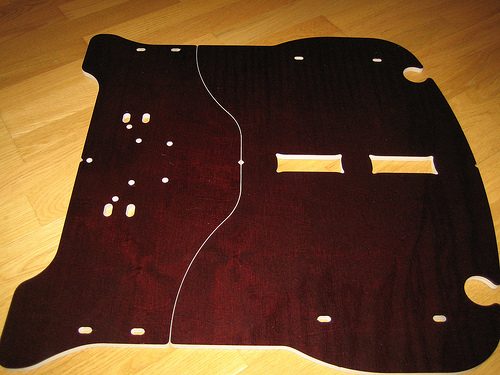
Moving to the next phase... I think at this point I have not saved much model pics or then I've deleted those at some point, only ones I could find (that are really close to the one built as a proto):

http://i308.photobucket.com/albums/kk341/Timppaq/GTrr/AFTERjpg-1.jpg

http://i308.photobucket.com/albums/kk341/Timppaq/GTrr/AFTER2jpg.jpg?t=1324069511

Which actually was to be my first prototype, and from which I learned tremendously. There's nothing as important as testing things in real life with these kind of things. You can always try to imagine how things will be / behave, but in the end you'll notice that there were many things missed in the thought process (that might even seem obvious now). Maybe some things did go as thought also, but in general was a great learning experience (behind scenes info: still haven't got the bill for the plywoods that actually were CNC machined & painted :D It was a little family company, and could I say the manager was very laid back. When I asked for the bill when I went to pick up the parts, he just said that I'd get the bill at some point.. :lol:)

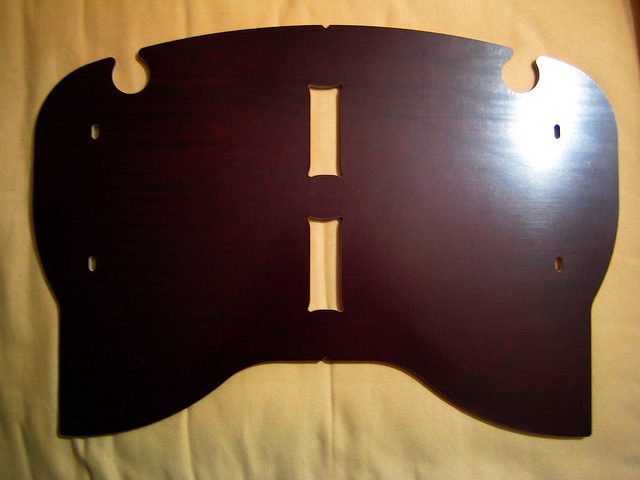
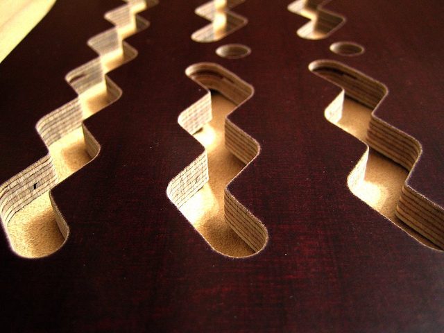
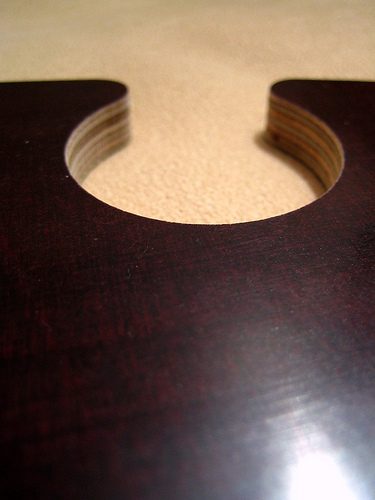
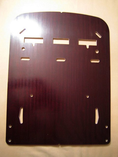
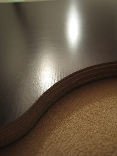
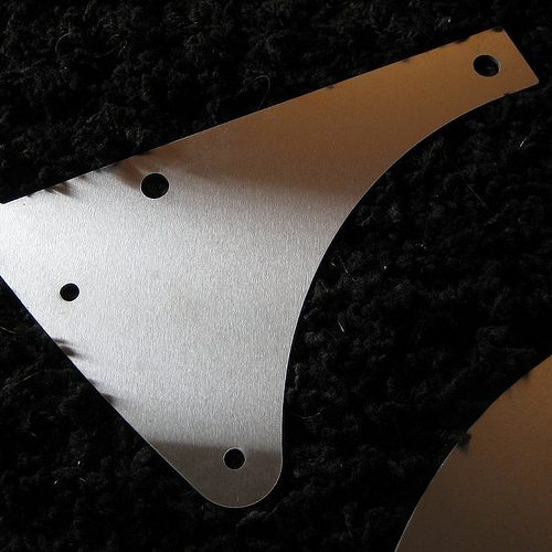
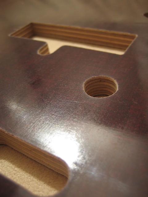
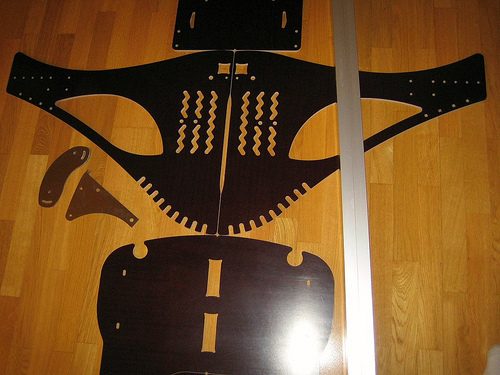
Here's pics of the real thing:

http://i308.photobucket.com/albums/kk341/Timppaq/GTrr/Picture072.jpg?t=1324069638

http://i308.photobucket.com/albums/kk341/Timppaq/GTrr/Picture077.jpg?t=1324070100

http://i308.photobucket.com/albums/kk341/Timppaq/GTrr/Picture068.jpg?t=1324070459

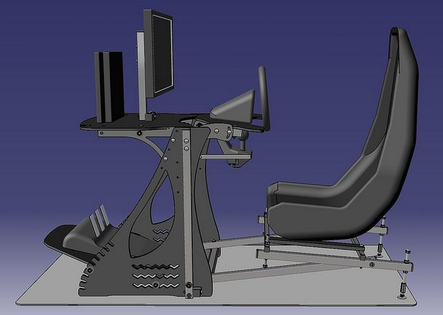
After that I think it took a good while to get the next one out. I tried to apply all I had learned and the end result proved that I did learn something. But I see clearly now that there were still a lot to learn (and I'm sure there still is).

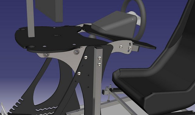
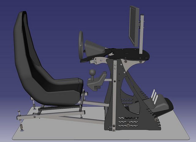
So this is what came out of that process.. (can't find any pics of the phases meanwhile)

http://farm7.staticflickr.com/6033/6378397507_993763dce5_z.jpg
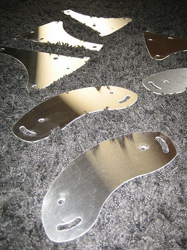
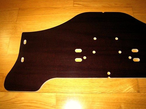
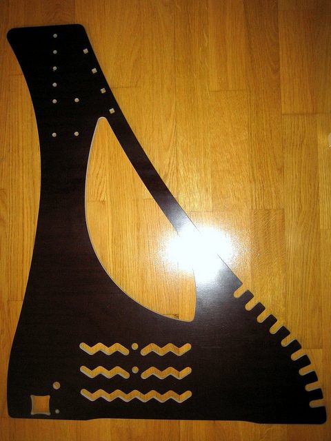
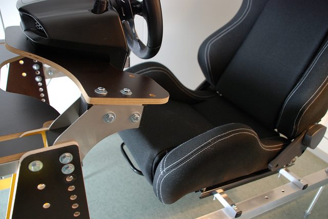
And the real:

http://farm2.staticflickr.com/1090/5103008262_57ebf43c64_z.jpg

http://farm5.staticflickr.com/4131/5061026914_4634140a7f_z.jpg

The end result with that one was really great. There were still many issues for me to take care of though, and that really came obvious only after I had put a few of them together & used one for a while myself. And I hope also that you notice the difference in looks with the real one and the 3d model. It's just a fact that in real life all these kind of things look much better and if I may say so when you see something in person that also surpasses any photo with almost the same margin. 👍

Even though everything that I wanted was possible (adjustment wise) & the rig was plenty sturdy (more than enough), the process for both was still much too complicated. Too many parts, too much hassle putting it all together, too troublesome to adjust. (still remeber the comment form Mr.Latte in the early days of the first thread - you were right :lol:) Can't even begin to think how the first model seen also here would have been like!! :lol: These things mentioned all of course meant there were a lot of unnecessary cost still built in.

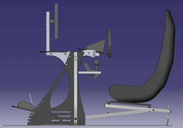
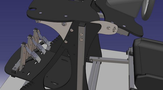
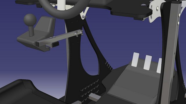
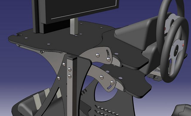
From here on I had a much clearer vision & knowledge of what to do and how. Here's some pics of the stages between the latest build model & the time I posted this thread.

http://i308.photobucket.com/albums/kk341/Timppaq/GTrr/ScreenHunter_08Oct261759.jpg?t=1324072838


--


http://i308.photobucket.com/albums/kk341/Timppaq/GTrr/ScreenHunter_01Oct311941.jpg?t=1324073481

http://i308.photobucket.com/albums/kk341/Timppaq/GTrr/ScreenHunter_04Nov031434.jpg?t=1324073377


--


http://i308.photobucket.com/albums/kk341/Timppaq/GTrr/ScreenHunter_05Nov111446.jpg?t=1324073649


--


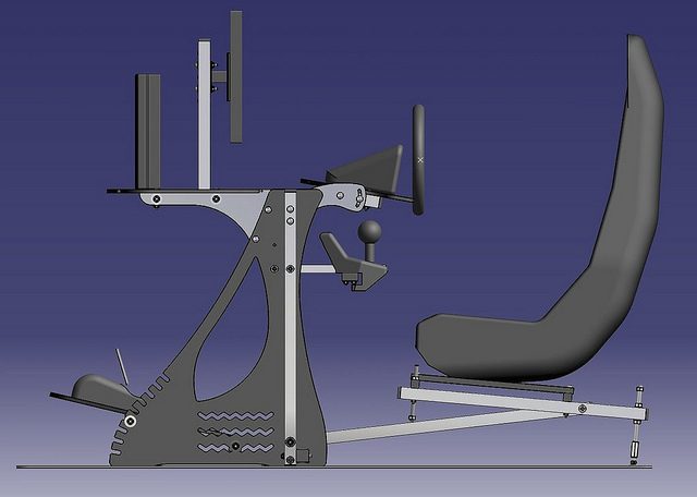
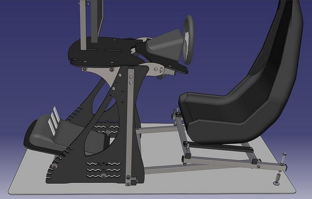
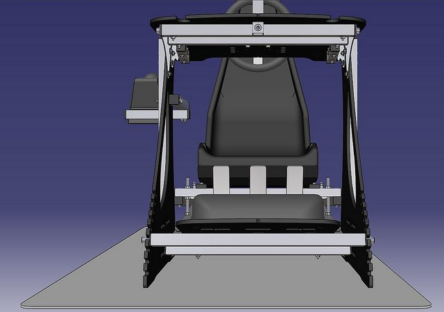
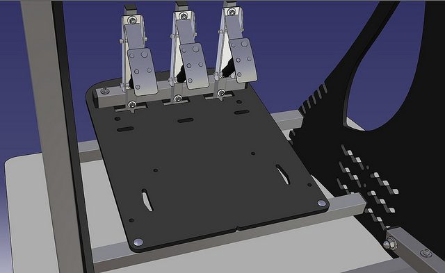
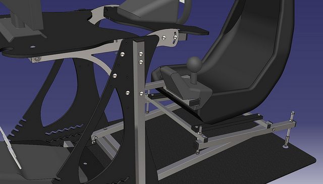
And this is the exact model I had for many months in my HD (when I had a long break with this project) Before suddenly getting a brain(fart)storm and suprisingly getting the spark back to keep this going..

http://i308.photobucket.com/albums/kk341/Timppaq/GTrr/ScreenHunter_08Jan201728.jpg?t=1324073995

At this point I still had a few important things that I thought I had not found an answer for and still were bugging me.

- too complicated to adjust the height of the seat (I know not very important maybe for many, but still doing this whole thing basically for myself and against my own requirements) (If you're wondering, it was complicated because you had to completely remove the seat part of the 'main rig' and change the hole that the seat part is connected to).

- the (almost) horizontal 'seat alu tube bars' (without a better word for it) going to the main vertical beams were still too much in the way of getting into the cockpit & out of there (tbh, in real world there really was no issue at all imo, but still hoped to come up with something better in this area..) Luckily I killed two flies with one strike as changing this part of the structure as it is now changed the adjustment of the seat angle/height to something much easier & at the same time took most of the obstruction away.

- too many parts. There has to be a way to do things more simple but as I had thought about this for so long, my brains were jammed basically. So the break did good for me I believe, as I did manage to lower the part count on most parts of the rig. The changed way of adjusting the seat angle / height does add to the part count number but the benefit far overweights the nominal amount of the parts, imo.

- the main 90deg. joint of the base frame. With 2 drilled holes there would be 2 problems: 1. Is it reasonable to require really accurate drilling from a DIY'er? 2. Would the needed tightening force deform the alu tubes?

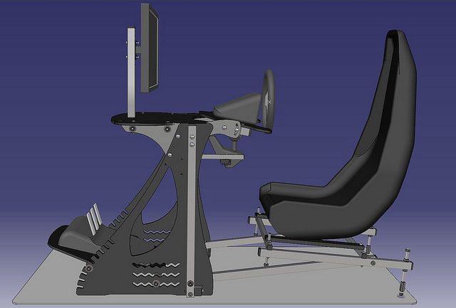
All these lead to the latest model, that I opened this thread for. There are still some slight question marks in the air though. Will it all be/behave like I imagined? I will be taking a sight a 'risk' once I order all the parts, because you never can foresee everything - you'll see when you'll put one together .

.
.
.
.
.
.
.
.
.


So just for fun here's a side by side comparison between the very 1st concept & the current one:

http://i308.photobucket.com/albums/kk341/Timppaq/GTrr/BEFOREjpg.jpg http://farm8.staticflickr.com/7010/6515946621_bf482ed5f0_z.jpg


Of course, I'm still to see if I've got it more right this time (in relation to the prev. real life build), but based on the previous experience with these experiments I strongly do believe so.

One thing I do notice, this all again proves the point that you always come up first with the most complex solutions for most problems / issues. A simple solution is usually the hardest one to do! :lol: I've seen the same thing happen with my everyday job as well.

At this point, I've modelled over 250 parts for this project overall and must have used 500+ hours (through 2 years) thinking about it. Sounds like a lot to me, but as the saying goes in here - you can't get far with a moped, and even if you do, not very fast (it seems :ouch:))
Even if I say it myself, I do see some improvement through time though, thank gawd.


Disclaimer: this post may not be here tomorrow after I wake up and sober up! :P
 
Last edited:
Timo, firstly, outstanding work 👍 The concept is very nice (all iterations) and reminds somewhat of a high end rack for stereo equipment. All the exposed joints and laser cut sections really appeal to my engineering sensibilities 👍

I think the VESA mount is essential, even just for yourself as you may want to move to a larger screen (32") in the future. However, when that happens, you may also want to move the screen back or forth and I don't see much flexibility in your design for that (unless you got a new horizontal member made that has the VESA plate welded to it). Have you considered simply attaching an aftermarket screen mount arm to the table? I use this one at work that uses an elbow joint to allow the screen to move in and out relative to my seating position, and it is also height adjustable. You could also use the wall mount one to attached to the vertical post that comes out of the table in your current design.

The only other think that comes to mind is a small tray mounted on the side for a laptop or keyboard (maybe next to the gear lever?)

Looking forward to seeing it built 👍
 
Last edited:
Thanks for the nice words Jon,

I think 32" would be close to being too big. Of course a matter of taste, but 24" seems to be close to perfect size imo. (My current screen is actually 22" btw.) But it is a possibility that one would put a 32" screen there and that should be taken into consideration as well. There are now those two different positions, which I did reposition a little. Now the distance from the screen surface to the wheel rim center point is ~500mm or ~365mm. I believe 0,5m is enough even for a 32":

http://farm8.staticflickr.com/7160/6553345959_35820ee9d6.jpg

http://farm8.staticflickr.com/7146/6553345857_a454668bea.jpg

http://farm8.staticflickr.com/7160/6553367971_1bf897db4e_z.jpg

And from the start I've always kind of thought that if you want to use VESA mount you could just use an aftermarket arm etc. for it. 👍 Now I did include the vertical post possibility there, but it will still require a 'wall mount'. This is beneficial because the wall mount probaply is somewhat cheaper than a proper legged one.

The keyboard tray I do believe will be much better to use an aftermarket holder. Will be much better to use & to look at.

On other news,

Got all the holes that are to be predrilled now into the model:

http://farm8.staticflickr.com/7009/6553346033_cd0c7e1502.jpg

http://farm8.staticflickr.com/7003/6553346111_5a40480687.jpg
 
Last edited:
Yes I'm using a 24" at the moment and it is a similar distance to what you have mentioned. Mine's a little low though which is probably why I'm lusting after a 32" :lol:

I won't ruin your thread by showing you, but you can see a picture of it in the WRS forum!

Have a good Christmas 👍
 
Ok, got everything ready to order the parts. Just need the answers for the costs and will order a set as soon as I have the funds. This may or may not take a while though, as I need to take missus to a holiday for her BD & as a Christmas present also.. Might have to see at what figure that'll total.

Btw, if somebody should be interested buying a set of the extra parts (will need to order 10sets), I'll sell these at cost. So won't be making any money out of this all. I just need the extra sets to bring the shared cost down, quite significantly in fact. Either way I will order the 10 sets even if I don't have anyone with me at the time of ordering, and shall just see what I'll end up doing with them :P (need one for me really bad).

But as I said, no timetable to confirm yet.

This is how the parts will look.. (slight changes here & there - basically the same anyway. If you're wondering about the weird shaped holes/openings, they are just merged normal round holes to bring down the total amount of openings)

http://farm8.staticflickr.com/7167/6673791443_f88f4f6a99_b.jpg

http://farm8.staticflickr.com/7152/6673791595_07f54f1b6c_b.jpg

http://farm8.staticflickr.com/7022/6673791297_e2a012732c_z.jpg

EDIT,


Just for fun, here's a pic of the naked "skeleton" of the rig. In other words, just the alu tubings in their right places:

http://farm8.staticflickr.com/7026/6672103579_e903d60cf4_z.jpg

Doesn't look that rigid there I must admit :lol: But I have faith! (and some experience as well luckily :D

Here's the tubings lined up:

http://farm8.staticflickr.com/7009/6672064143_a2daae385c_z.jpg
 
Last edited:
http://www.kauppasatama.fi/tuotekuvat/big/arm-417.jpg

I think I'm going to order that one for the "wall mount" option. Not too pricey either, 14,90€.

Has little adjustment up, down, left & right 👍


edit,

or maybe this one,

arm-943.jpg


wouldn't eat as much the distance to the screen...


edit 2,

oh the last change I did was the little reshaping of the steel plate for wheel adjustment..

So this IS the final model (soon to order really)

6689186931_350aa2b863_z.jpg


6689186565_22da18cd09_z.jpg


6689186735_e5cd78309b_z.jpg


6689186843_f47290bf5e_z.jpg
 
Last edited:
Just figured out that I could possibly use the seat base independently and just put the stand part away if needed. I'd just need to add a pair of those adjustable feet to the front as well to prevent scratching the floors.

This is something that I had in mind earlier, to have the possibility to hide the main frame and keep the seat out for other gaming etc., but I kind of forgot it at some point. Ok, it'd be a bit weird looking maybe but still possible :P

6400617967_a314c7262d_z.jpg
 
Juct a quick update as I got a message yesterday, the parts are ready for pick up. :D Too bad I'm sick and can't get them before next week but finally this is moving forward.
 
Last edited:
Hello Timo! I noticed this thread only now, great to see the work continuing 👍 Though I have to say, that you won't get a customer from me, I see no need to upgrade from GTrr 1.0 :P I still have only positive things to say about it. Sure, it's a bit effortful to adjust like you said, but once you get it right, there's no need to touch it. Actually my biggest grind of the version 1.0 tells quite a lot of how good that already was. It's the bolt heads on the screen "table". If the screen leg is solid, it limits the positioning possibilities unless you use some sort of extra parts under it.

I got some ideas from this thread too. VESA mount would be a good update for this one too, it would give more room for keyboard etc. I might implement it at some point.

Good luck with the 2.0!
 
Yes! Got all the parts here with me (not the alu tubes though but the sheet parts), and they look great & very promising. :D I try to post some pics a bit later tonight.
 
I couldn't get really good pics as there was no natural light anymore (and I have a crappy camera only atm) but will do proper & bigger ones later. Maybe you get some idea of these anyway.

Was really lucky and found a good supplier that can make me these in sets of just 2 (min), before I needed to make around 10 to be affordable and that required a bit too much money to burn on a one go.

All cut with a water jet, with 4200bar cut stream :eek:

6871764425_4e48f640a0.jpg
6871762563_f565e1eefa.jpg

6871761587_dcd219e410.jpg
6871757103_48395f0bb0.jpg

6871835537_2f4026e47f_z.jpg
6871868239_f8d4451d69_z.jpg

6871885829_589a295ec6_z.jpg
6871940127_7425cc026d.jpg

6871905719_fd52670a6c_z.jpg
6871767839_340b7bed28.jpg

6871754911_2119ef2a49.jpg
6871814607_d4e8616b86.jpg

6871769863_144a01f9cd_z.jpg


Sorry about the dust etc. in some pics.

So eventually it'll be like this:

6689186565_22da18cd09_z.jpg
 
Last edited:
A couple more of the parts I didn't show yet properly at least..

6887573483_35bc10e3fa.jpg


6887589563_555665ee08_z.jpg


Search for the alu tubing is going on at the moment, shouldn't take too long now.
 
Beautiful quality there Timo - did they let you observe the water jet cutting? Such a simple concept and it does give amazing results.
 
Thanks mate :cheers:

I did go there a bit early and was allowed to see the last phase of cutting the stainless steel parts 👍 The machine is pretty amazing, I heard it's only of it's kind in Finland atm, and can watercut at least 170mm of steel with a straight cutline :eek: (saw a leftover piece of a hole that was cut to a 170mm steel piece)

I'll get the aluminium tubes on Tuesday it seems. :)

edit,

also I ordered this for the screen mounting:

arm-943.jpg
 
yay! Got all the main parts here with me as I just got the aluminium tubings. They're really nice and it's clear that the size is just perfect for this purpose (30mm x 30mm) No flexing at all! :) Just need to go shopping tomorrow for the screws etc. and start making things happen. :)

6800567954_66c37a6dfe.jpg
6946673881_8e9e5de52b.jpg

6800568448_aca4651f9c.jpg


6800579810_cfe4aabc11.jpg
6800601368_037b7f4b78.jpg
 
Back