- 9,589
- GTP_DelphicR
- Esoterik1
///Delphic Reason's GT Cockpit DIY\\\
Well, I stumbled across a good deal for a Black Leather Universal Sport Seat (see attached). So I decided to stop procrastinating and start building my cockpit. I have been using an Obutto Ozone, and it has been a fantastic budget cockpit. However, it lacks the adjust ability/customize ability that I would like for that extra immersion in my various types of racing games.
I will keep the top of this page updated with the current status (and pictures) of the build.
UPDATE (08/17/10):
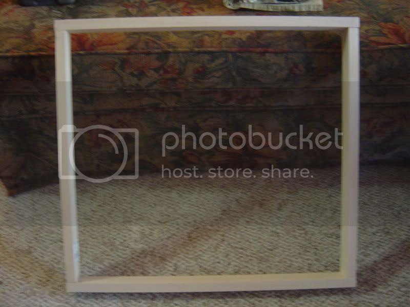
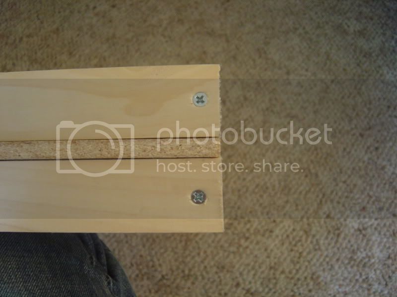
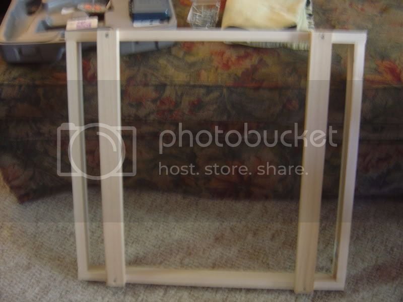
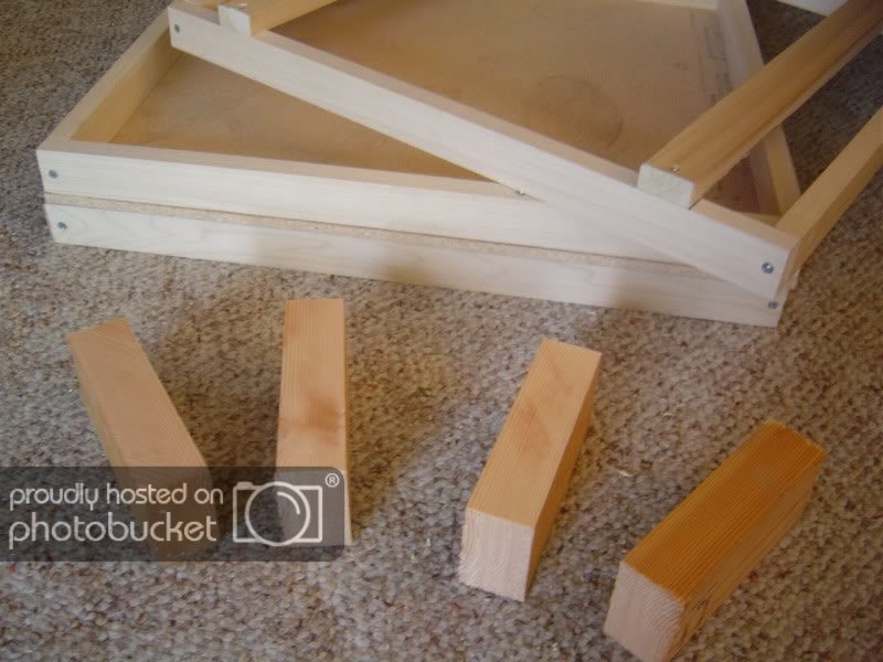
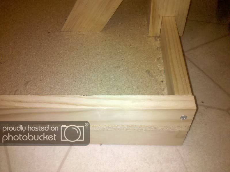
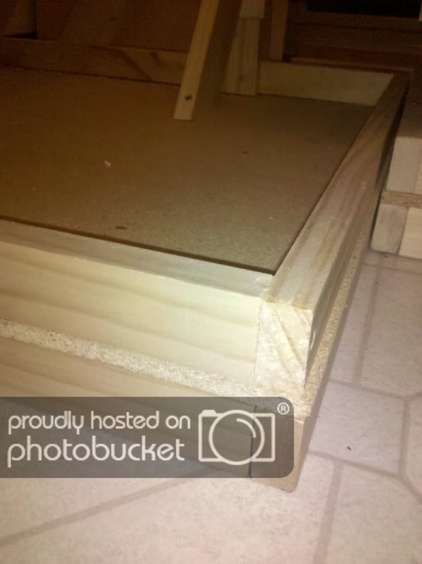
1. I started off by building 3 box sections like the picture below, using 1x2's (21 x 22.75"):
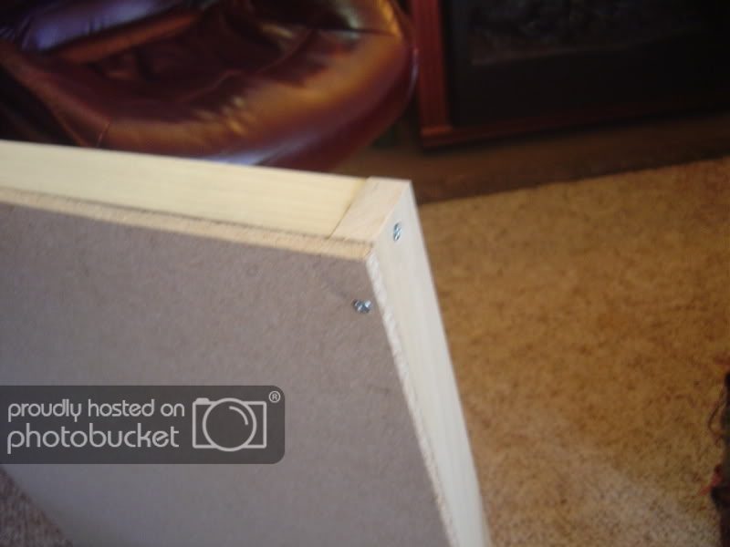
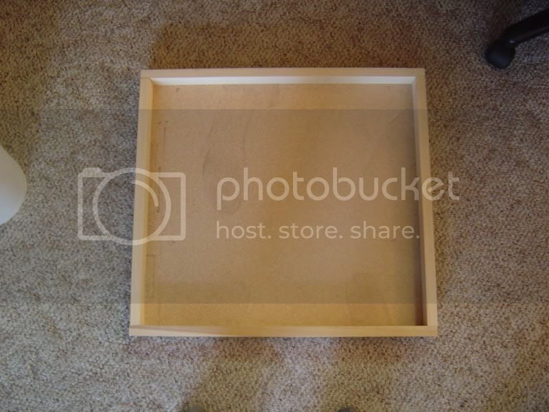
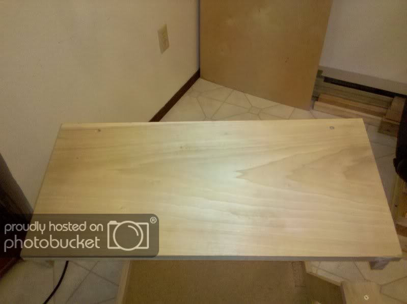
2. Next I cut some particle board (carpet underlay) to the dimensions of the outline of the box (21 x 22.75") and attached the two together using 1 1/2" screws:
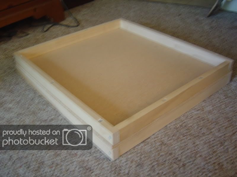
3. I attached another of the box outlines to the other side of the particle board:
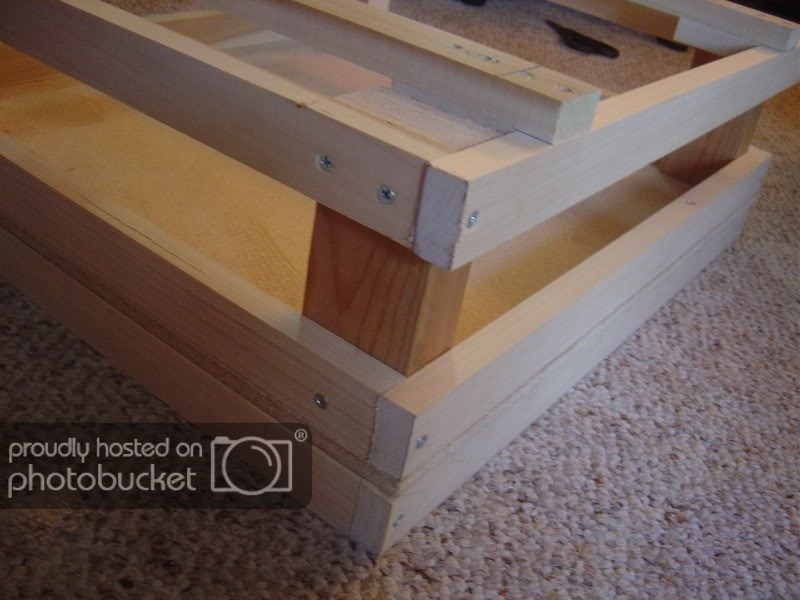
4. I took the 3rd box outline I made, and used it as a mounting point for the seat. I measured the sliders and attached two lengths of 1x2's at 21" long (these 1x2 sections will be where I attach my custom Buttkicker mount):
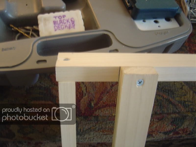
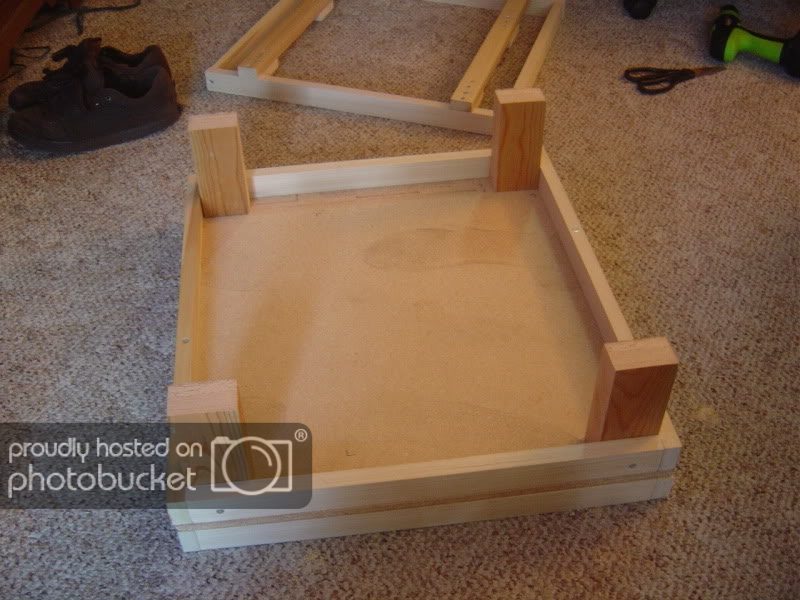
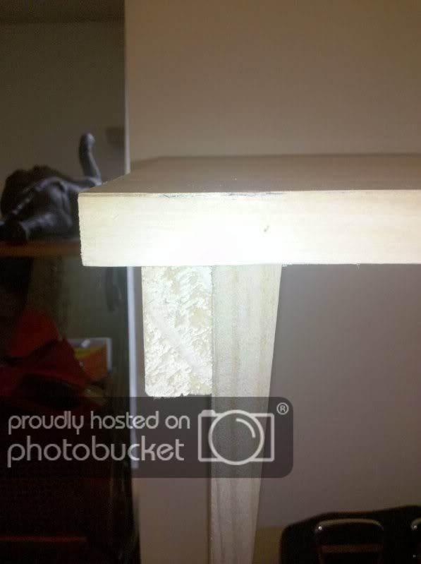
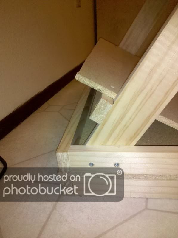
5. So, now we have our base made up of the 2 box outlines attached to the either side of the particle board, and our seat mount attached to the 3rd box outline. So, I cut some risers out of 2x3's. I cut mine to 6", but you will want to cut the risers to your preferred seat height.
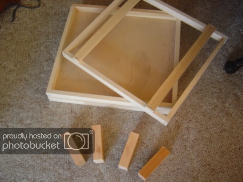
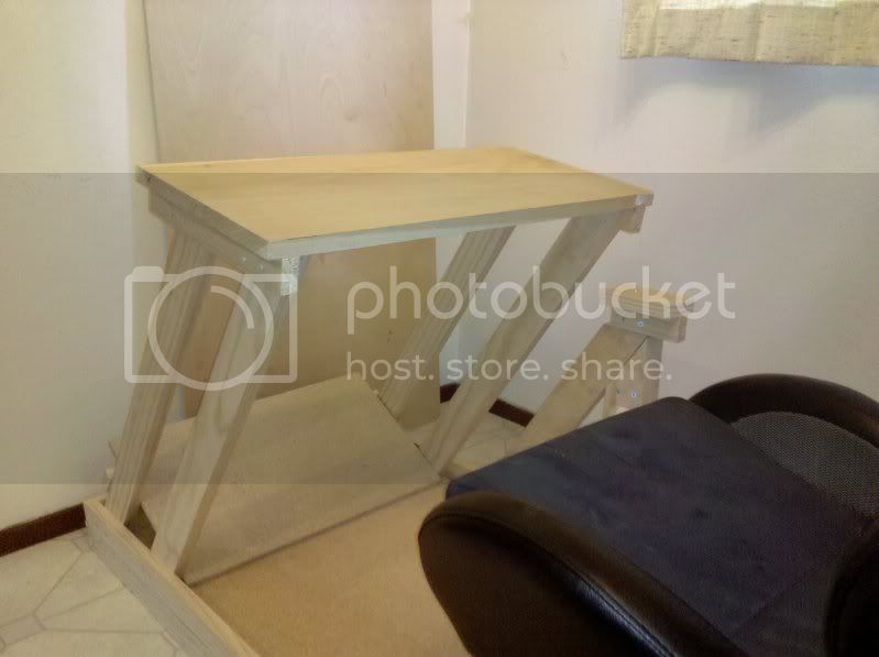
6. I then attached the risers to the 4 corners of the base, and then connected the top section to the risers via some 2" screws (2 in each board for strength):
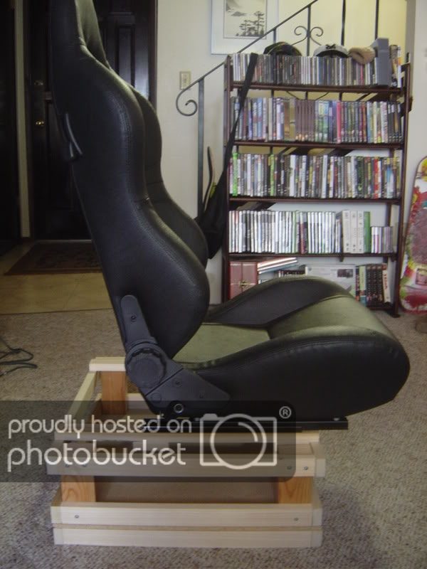
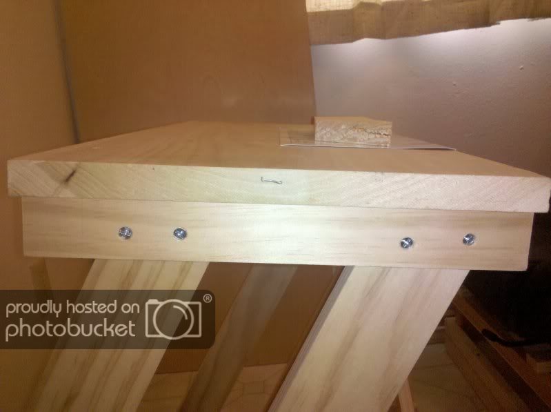
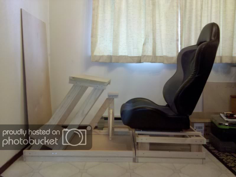
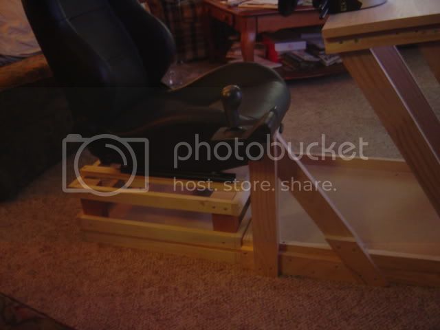
7. All that was left to do now was mount the seat. I used 2 1/2" bolts, washers, and lock nuts to secure. Your seat application may be different. I also added short 1x2 sections under the seat mounts for a beefier secure connection:
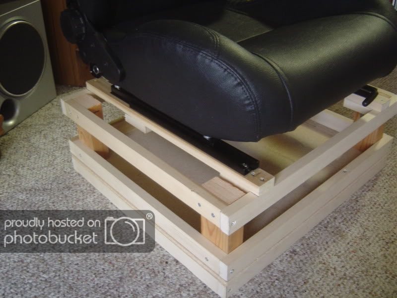
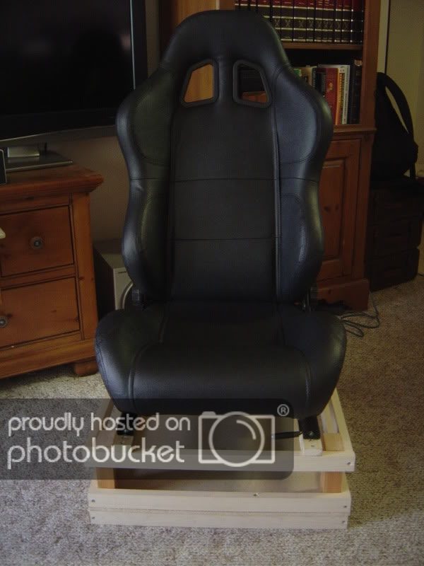
Seat fully back:

Seat forward:
UPDATE:
Now that we have our seat ready for racing, we need to focus on the front section that will contain the pedals, shifter, and most importantly... the wheel.
Here is an example of the finished front section:
Notice that the base of this section was constructed using the same method as the seat base. Therefore, the width will be the same as the seat base. So...
Cut out your particle board (or whatever you would like to use in it's place) to 22.75" x 34.5"
Next, cut your 1x2's that will frame the top and bottom of the base piece you just cut. Again, the shorter pieces will be the same as the seat base.
So, cut 4 boards at 22.75", and 4 boards at 31.75". Once again, I find it easier to then connect the frame pieces together before attaching them to the base. Then attach the frame sections to either side of the particle board using 1.5" screws.
Example:
Next, lets construct our wheel tray, before moving on to the uprights.
Example:
I purchased the board for the wheel tray at Home Depot, so there was no cutting necessary. You're luck may differ. The dimensions are 24" x 11.25" x 1" thick. You should be able to find something along those dimensions at your local lumberyard. Now, cut two 1x2's to a length of 11.25" to match the tray. These will be what we attach our uprights to (this is why the wheel tray should be finished before the uprights).
Example:
Set the 1x2's in 1/2" as shown in the pictures below:
Attach with 1" screws from the top of the wheel tray. That's it...
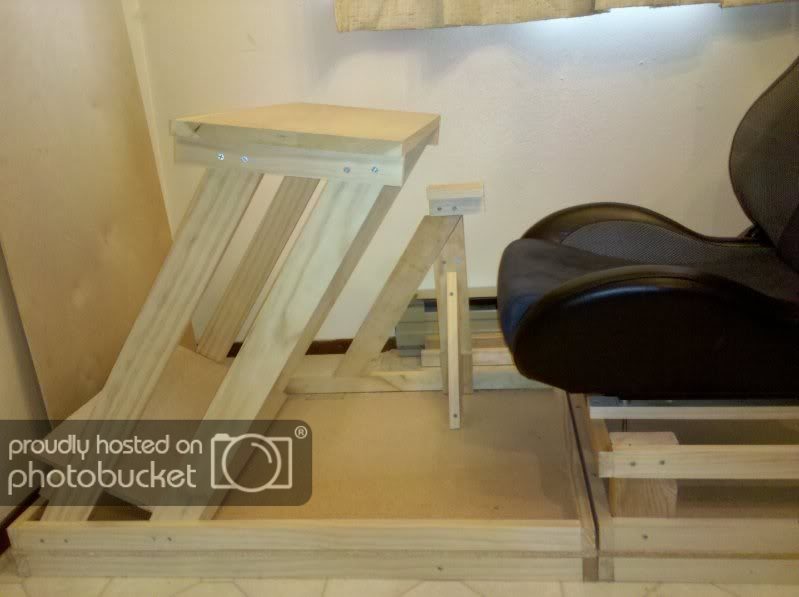
Now that we have our wheel tray completed, it's on to the upright supports.
Example:
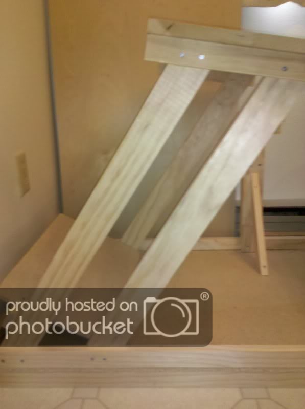
The upright supports are made from 1x3's at 27" tall. To get the angle, just place the board in the position pictured until the top corner of the base of the 1x3 is lined up with the top of the base frame (it sounds more complicated than it is).
Here is an example:
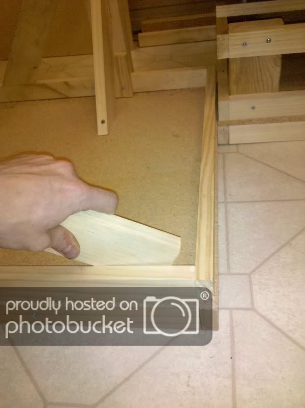
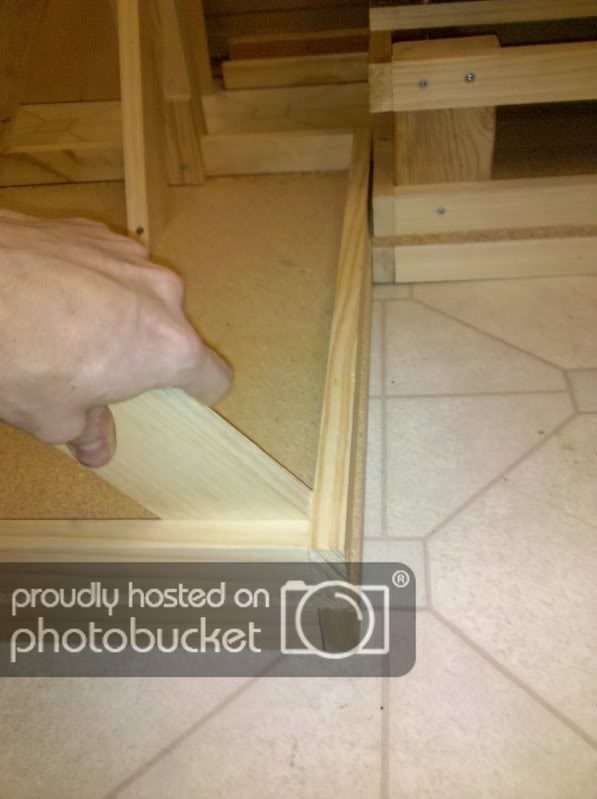
Now grab a pencil and, using the top of the base frame for a guide, mark a line and cut. This will give you a good angle for the uprights. For the second uprights (nearest the seat), just clamp the first uprights in place, and use that angle as a guide:
Once again, marking a line and cutting. Now, leave a space between the uprights of 4".
So, now you have your 4 uprights, but we're not done yet. We need to figure out the angle for the wheel tray, and thus what angle the top of the uprights need to be cut to.
Take your finished wheel tray, and clamp your wheel to it. Sit in your finished seat and hold the wheel (and thus the tray) in front of you at the desired angle you want the wheel to be at (now this part will be easier with a friend, or a few clamps) Using your wheel tray as a guide, mark the top of the uprights at your desired angle. Unfasten all the clamps and remove the uprights. Make your cuts, and then install them back into the base using 1.5" screws, and remember to space the two uprights 4" apart.
Now you just need to place your wheel tray on top of the uprights, and fasten them together using 1" screws.
You're done with the wheel stand portion of the build. Now, on to the pedal tray...
Take your particle board (you may want to use something else if you're planning on painting these pieces. as it is, I will be adding automotive carpet to the particle board sections) and measure 19.75" x 11.25". This will be the tray the pedals will mount to.
Example:
Next measure a 1x2 out to 21.25". This will be the support for the pedal tray. You will have to experiment a little with the angle of the tray. Once you have an angle that suits you (you can also mount your pedals onto the tray at this point to help with deciding on an angle), attach the 1x2 just under the tray against the front of the uprights, using 1" screws.
Example:
Congratulations! You have completed the basic structure for the seat/front sections.
Now, on to the shifter mount...
COMING SOON (4/19/10)
NEW:
Here is the nearly completed cockpit (sans panels and paint, amongst other details) with Fanatec Porsche 911 Turbo S wheel/shifter/pedals attached

Currently with Standard Pedals
Side view of Shifter Mount
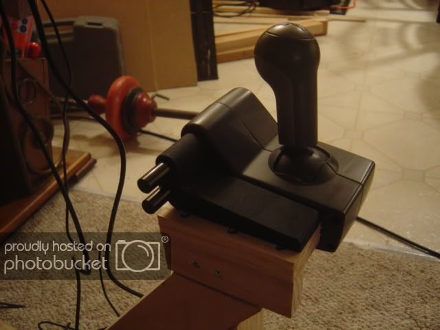
Close up of Shifter Mount
Next comes paneling, paint, decals, Buttkicker, etc...
Stay tuned!
")
Well, I stumbled across a good deal for a Black Leather Universal Sport Seat (see attached). So I decided to stop procrastinating and start building my cockpit. I have been using an Obutto Ozone, and it has been a fantastic budget cockpit. However, it lacks the adjust ability/customize ability that I would like for that extra immersion in my various types of racing games.
I will keep the top of this page updated with the current status (and pictures) of the build.
UPDATE (08/17/10):
Cockpit Update (Current State):
(i.e This is what your cockpit can look like if you follow the steps below)


Below, I will take you through the steps, I used, to build my sim-rig.
Part 1: Seat Base
(i.e This is what your cockpit can look like if you follow the steps below)


Below, I will take you through the steps, I used, to build my sim-rig.
Part 1: Seat Base
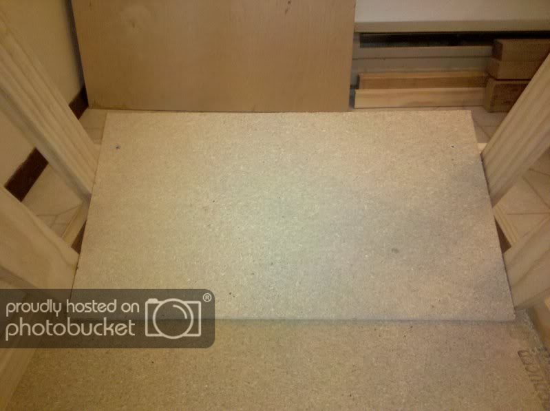
1. I started off by building 3 box sections like the picture below, using 1x2's (21 x 22.75"):
2. Next I cut some particle board (carpet underlay) to the dimensions of the outline of the box (21 x 22.75") and attached the two together using 1 1/2" screws:
3. I attached another of the box outlines to the other side of the particle board:
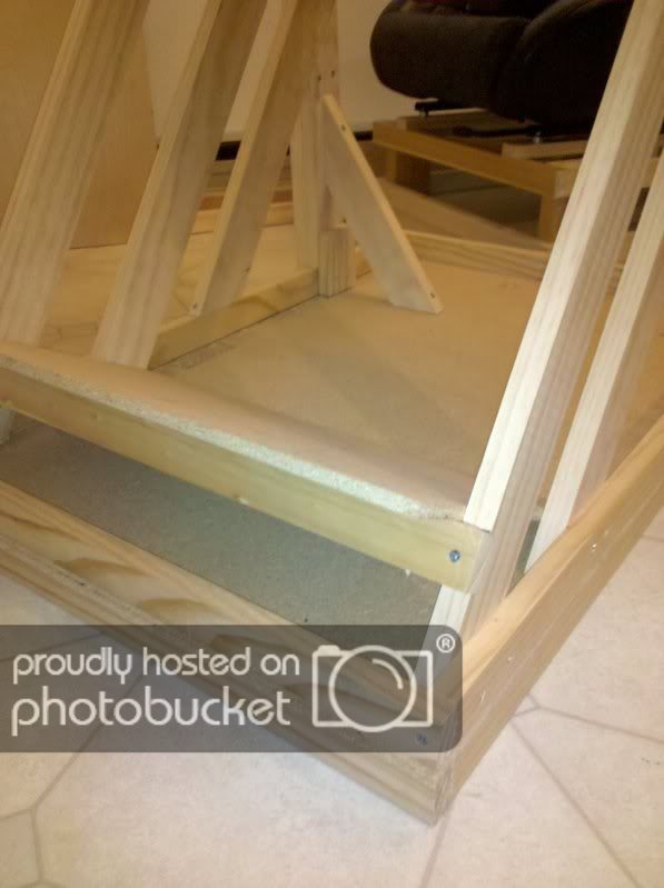
4. I took the 3rd box outline I made, and used it as a mounting point for the seat. I measured the sliders and attached two lengths of 1x2's at 21" long (these 1x2 sections will be where I attach my custom Buttkicker mount):
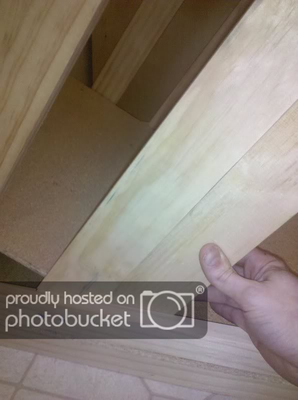
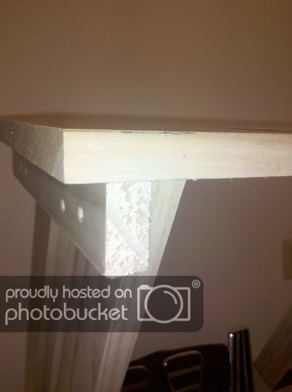
5. So, now we have our base made up of the 2 box outlines attached to the either side of the particle board, and our seat mount attached to the 3rd box outline. So, I cut some risers out of 2x3's. I cut mine to 6", but you will want to cut the risers to your preferred seat height.
6. I then attached the risers to the 4 corners of the base, and then connected the top section to the risers via some 2" screws (2 in each board for strength):
7. All that was left to do now was mount the seat. I used 2 1/2" bolts, washers, and lock nuts to secure. Your seat application may be different. I also added short 1x2 sections under the seat mounts for a beefier secure connection:
Seat fully back:
Seat forward:
UPDATE:
Part 2: Front Section (containing wheel/pedals)
Now that we have our seat ready for racing, we need to focus on the front section that will contain the pedals, shifter, and most importantly... the wheel.
Here is an example of the finished front section:
Notice that the base of this section was constructed using the same method as the seat base. Therefore, the width will be the same as the seat base. So...
Cut out your particle board (or whatever you would like to use in it's place) to 22.75" x 34.5"
Next, cut your 1x2's that will frame the top and bottom of the base piece you just cut. Again, the shorter pieces will be the same as the seat base.
So, cut 4 boards at 22.75", and 4 boards at 31.75". Once again, I find it easier to then connect the frame pieces together before attaching them to the base. Then attach the frame sections to either side of the particle board using 1.5" screws.
Example:
Part 2-a: Wheel Tray
Next, lets construct our wheel tray, before moving on to the uprights.
Example:
I purchased the board for the wheel tray at Home Depot, so there was no cutting necessary. You're luck may differ. The dimensions are 24" x 11.25" x 1" thick. You should be able to find something along those dimensions at your local lumberyard. Now, cut two 1x2's to a length of 11.25" to match the tray. These will be what we attach our uprights to (this is why the wheel tray should be finished before the uprights).
Example:
Set the 1x2's in 1/2" as shown in the pictures below:
Attach with 1" screws from the top of the wheel tray. That's it...
Part 2-b: Upright Supports
Now that we have our wheel tray completed, it's on to the upright supports.
Example:
The upright supports are made from 1x3's at 27" tall. To get the angle, just place the board in the position pictured until the top corner of the base of the 1x3 is lined up with the top of the base frame (it sounds more complicated than it is).
Here is an example:
Now grab a pencil and, using the top of the base frame for a guide, mark a line and cut. This will give you a good angle for the uprights. For the second uprights (nearest the seat), just clamp the first uprights in place, and use that angle as a guide:
Once again, marking a line and cutting. Now, leave a space between the uprights of 4".
So, now you have your 4 uprights, but we're not done yet. We need to figure out the angle for the wheel tray, and thus what angle the top of the uprights need to be cut to.
Take your finished wheel tray, and clamp your wheel to it. Sit in your finished seat and hold the wheel (and thus the tray) in front of you at the desired angle you want the wheel to be at (now this part will be easier with a friend, or a few clamps) Using your wheel tray as a guide, mark the top of the uprights at your desired angle. Unfasten all the clamps and remove the uprights. Make your cuts, and then install them back into the base using 1.5" screws, and remember to space the two uprights 4" apart.
Now you just need to place your wheel tray on top of the uprights, and fasten them together using 1" screws.
You're done with the wheel stand portion of the build. Now, on to the pedal tray...
Part 2-c: Pedal Tray
Take your particle board (you may want to use something else if you're planning on painting these pieces. as it is, I will be adding automotive carpet to the particle board sections) and measure 19.75" x 11.25". This will be the tray the pedals will mount to.
Example:
Next measure a 1x2 out to 21.25". This will be the support for the pedal tray. You will have to experiment a little with the angle of the tray. Once you have an angle that suits you (you can also mount your pedals onto the tray at this point to help with deciding on an angle), attach the 1x2 just under the tray against the front of the uprights, using 1" screws.
Example:
Congratulations! You have completed the basic structure for the seat/front sections.
Now, on to the shifter mount...
COMING SOON (4/19/10)
NEW:
Here is the nearly completed cockpit (sans panels and paint, amongst other details) with Fanatec Porsche 911 Turbo S wheel/shifter/pedals attached
Currently with Standard Pedals
Side view of Shifter Mount
Close up of Shifter Mount
Next comes paneling, paint, decals, Buttkicker, etc...
Stay tuned!
Last edited:
")


 And set off with the intention of making it a strong as possibile. We added the metal supports as it was a little wobbly before. They really made a nice difference. And yeah, it just ended up being very stable.
  get together) had 2 BK Gamers hooked up to his cockpit (one on each side (externally mounted)). I'm not sure how he hooked it up though. Seemed to be working well with GT4 and GT5


