Custom G27 controller programming

sesselpupser

Bearded Member
Premium
9,043
United Kingdom
United Kingdom
neema_t
So I was watching this:


And I thought hey, maybe the G27 has a JTAG header or similar debugging interface, I wonder if it would be possible to have a poke around inside the microcontroller and see if there's any unused capabilities, I/O or similar?

The problem is I'm currently a long way away from my G27 so I can't have a look myself, so I'm wondering if any G27 owners either already know or could take a look at the microcontroller and let me/us know what the label on it says? Basically I need to know what's under the sticker that says "KS3" on the biggest black rectangle in this photo:

5120265086_789f7d2f4d_b.jpg


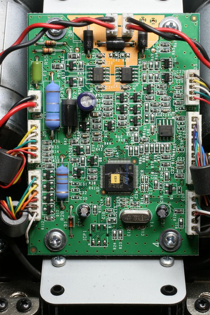
Maybe it's a dead end but that "ICP1" header at the bottom might be JTAG-compliant so it could be worth investigating...

Thanks!
 
Lucky for you I have one in pieces right in front of me to check (well it was in a box).

72F651
AR6T1
991NC'V5
MYS 99 324

My board looks a bit different than yours by the way, or is that a G25 pic above maybe? I can check the code for the G25 if you need it too.
 
Last edited:
Lucky for you I have one in pieces right in front of me to check (well it was in a box).

72F651
AR6T1
991NC'V5
MYS 99 324

My board looks a bit different than yours by the way, or is that a G25 pic above maybe? I can check the code for the G25 if you need it too.

Thank you! I'll see what I can find, but it's not impossible this is a custom microcontroller that the manufacturer (STMicroelectronics) hasn't released the datasheet for but I guess we'll see.

It might be a G25 board in the photo but I expect they work mostly the same way so if I can find the datasheet for either microcontroller it should reveal the debugging opportunities for both the G25 and 27, probably also the DFGT, but that's just a guess based on how similar the two wheels are.

Edit: Well, that was easy! Datasheet here. I haven't had a look yet but from the description I can see it does USB natively and supports SPI and I2C, hardware UARTs like that are used to interface with other ICs but I can't see any on the board above that would be complex enough to require it, but the shifter does have an EEPROM on it so I guess that's how they communicate. If it were possible to extract the code from the G27 (which is doubtful) it would be quite straightforward to get it to communicate with other devices like a bluetooth module for wireless control (but not wireless power of course, unless your last name is Tesla) or maybe you could hook the RPM info into a real tach or something. Not sure why you'd do that because at 8 bits you get 256 steps so it'd look weird, and that's assuming it samples more data than it requires (since there's only, what, 8 LEDs on the wheel so you'd only need 3 bits for that).

Still, it's a potentially productive thing to daydream about while I'm at work so that's cool.

Edit again: If that is a G25 in the photo, they use the same microcontroller or at least very similar ones, you can read the first line and first two characters of the second. I wouldn't be surprised if the G29 used the same again.


Edit 3: The Changening: I've done a little reading and found two probable dealbreakers; there is no in circuit debugging for the ST7265 family (certainly no JTAG!) and there's read out protection on the Flash memory so there's no way to make it dump the memory contents if that has been set, I don't think there's much chance it hasn't been enabled though. I also don't have an ST7 in circuit programmer with which to test it and they cost a fair bit.

That means to get a look at what the G27's processor is doing you'd have to physically delid the actual microprocessor (either mechanically with a chisel or with fuming nitric acid which is exactly as nasty and difficult to obtain as it sounds), find a suitable data line on the silicon and probe it... That requires a specialised microscope and micropositioner tools that are a little out of my price range!

So basically editing the programming of the G27 is out of the question. Sniffing the USB traffic would be the next thing to try, the FFB is really the only thing that can't be easily replicated after all.
 
Last edited:
I was wondering, how hard would it be to develop a FFB enabled controller? Talking about the processing/software side of it here, it's basically just a generic HID device. The more I read about it, the more complicated it seems though. :lol: But it has been done, just looks like nobody is willing to share the source code.

It would be nice to have a controller with full access to all of the I/O including motor control and it's position feedback, just so it would be possible to use it on pretty much any sort of hardware, servo motors, regular DC motors with an analogue or digital position sensor, brushless motors etc.

Yeah, it's probably quite tricky; you'd have to have drivers that hook into whatever you're playing (which means whatever you're playing has to make the data you want available) then send the data, whatever it is, to the USB device. Generic HID devices do upstream easily but downstream stuff like feedback and vibration will either mean presenting the controller to the drivers as something else (as in, trick Logitech's drivers into sending G27 feedback data to something that isn't a G27) or writing your own drivers. While I have no idea how to do either, since I'm much more into hardware than software I feel like the former is more within my reach.

That said, Xsim is designed to output all this data to external devices like custom racing wheels, dashboard accessories and motion rigs so if you can get that working it'd be much easier. But I want to build a custom wheel that hooks into the Logitech drivers (mainly because compatibility is so good), except I want control over the microcontroller so I can make it do more.
That's something I was wondering too. But aren't there "driverless" FFB wheels? I might be completely wrong here, but doesn't the G25/27 work without the Profiler aswell? Either way, yeah, using already existing guts of a DFGT/G27 and the like is a more effective solution.

That's an idea I've been on and off pondering for several years now too. Getting a suitable punchy motor for FFB, hooking it up over belt drive and having Logitech guts controlling it. Just that the position feedback and having no software processing control over it would be a pain with ensuring the mechanical locks and proper encoder drive ratio for it to calibrate properly. That's way many moving parts to incorporate. I was thinking more along the lines of having a microcontroller between the encoder and the wheel controller board and then using an industrial rotary optical encoder plus a separate once-per rotation optical gate to find the center. This way it'd be possible to program it to send the wheel controller whatever impulses it wants to see to calibrate and get rid of both the mechanical locks and the need to have a precise encoder to wheel gear ratio.

The main possible issues I see is the microcontroller not keeping up with the data stream seeing as the encoders in most wheels are pretty high geared with many slots. If it's constantly missing pulses then it's pretty much useless. Things like Arduino bootloaded AVRs aren't the fastest in sending high/low signals as far as I know. This'd need more investigation though.

Anyway, I'm eagerly waiting for updates on your build. :P
 
@Jet Badger I did have a thread about a belt drive G27 conversion I was working on but I've since had to shelve because I moved out of my parents' place so I've not been able to afford to finish it, besides I have very little time for gaming now anyway as I work six days a week. That whole project was meant to be a sort of preparation for a high power motor conversion anyway - the stock motors are loud enough when the cores start rattling because of the helical gear axial thrust, so belt drive is essiential - so I've also spent some time studying how the microcontroller drives the motors, that looks to be a straightforward H-bridge with complimentary pairs of P and N-channel MOSFETs; I need to sniff out the PWM signal to work out the slowest possible replacements because, typically speaking, the higher the power handling of a FET, the slower the switching capability.

Anyway, the final piece of the whole puzzle would be to roll your own control board that mimics the G27 so the PC sends the feedback data via the highly compatible G27 drivers, that way you can control all sorts of things and if it dies you can just flash another MCU, grab another FET or DC motor, whatever you need. It's a big job, though!
 
I know, I've been following that thread for a while :P

Does it matter what exact sort of MOSFETs you use for the H bridge though? Even if it's a relatively powerful motor, having in mind it's one with lower stall current, it's not on full power most of the time. Just get whatever cheapest adequate ones you can get and tap into the gates of the ones on the PCB. The switching speed seems more of a side effect.

Atleast that's the way I'm thinking. :)
 
I know, I've been following that thread for a while :P

Oh, I haven't checked it for some time, you might've even posted there but I've probably forgotten by now!

I think the FETs' switching speed will matter, I haven't tested it but I expect if their switching speed is slower than the period of the MCU's PWM signal (which is F_cpu/64 - assuming the MCU's clock is 1:1 with the 12MHz crystal on the board that's 5.33us, but I've had a couple of beers so I'll check again tomorrow) then they'll never switch fully 'on'. I think, anyway. According to the datasheets I've found, the MOSFET ICs are either IRF 7342 and IRF 7103 or 4951GM and 9977GM (my G27 has the latter, but I've seen people discussing the former), the 9977GM's FETs switch in the low double-digit ns range (look at the characteristics between turn on delay time and rise time).

Anyway, because shopping for specific components is such a pain in the arse I'm happy to ignore that whole thing for now and focus on the USB stuff, I've got no idea where to start but I'm looking into it now.

Edit: I'm actually sitting here, studying the photo of the PCB I posted to try and decipher the SOT23's SMD codes. So many components are marked W04... I've at least figured out that the vertical row of SOT23s that are marked as diodes on the silkscreen are marked KJE which corresponds to a pair of BAV99 switching diodes connected in series.

I'm going to bed!

Edit again: So now I'm looking at it again and I think the two SOT 753s in the top right corner are NXP 74LVC1G08 2-input AND gates, at least their marking codes, packages and ground pins match but that's easy enough to test anyway.

That brings me to all the other SOT-packaged transistors; there are quite a few SMD devices with "04" and "06" marking codes but I've only seen NXP datasheets that mention a letter prefix (which is the manufacturing site code, in the photo they're all "W" but I can't find a source that lists their codes). Combined with the fact that I'm quite sure those ICs in the top right are NXP, I'm pretty sure those transistors are also NXP which means the W06 ones are PDTC124EU NPN digital transistors and the W04s are likely to be PMSS3904 NPNs, but that's kind of just speculation at the moment.
 
Last edited:
I tried at math.

12MHz is 12,000,000 counts a second, an 8 bit MCU counts up to 255. To calculate the shortest possible PWM period we divide 255/12x10^6 = 21.25us (also frequency of 12x10^6/255 = 47kHz). If we want 1% duty cycle precision over that, 21.25x10^-6s/100% = 212.5x10^-9s. That's at least 212.5 nanoseconds per 1% of duty cycle. All of the few common 100W+ MOSFETs (IRFZ/IRLZ44N, IRF540, etc...) I checked list rise/fall times well under 100ns typical. Being pessimistic and giving it some room, let's say it's around 150ns maximum - that's still well under 212ns, not forgetting that that is assumed under maximum possible frequency, which might very likely be pre-scaled and be at a lower frequency than 47kHz, resulting in longer possible switch time. Hooking up an oscilloscope would be one way to know for sure. Also all of this might be completely wrong because I suck.

Edit once more: yeah, that's wrong :lol: Didn't check the datasheet, your calculation was right. 12MHz/64 = 187.5kHz, yeah, it's a 5.3us period. That's 53.3ns per 1% of duty cycle. But then again it could be slower than that depending on how it's programmed.

Another thing to consider is the gate-source voltage needed to open the transistor fully. Unless they're logic-level ones, they usually need 9-10 volts or so do that. Looking at the datasheets of the IRF7342/IRF7103 it looks like pretty generic properties for a FET. I'm guessing it must be using additional transistors to amp up the voltage from the chip before going to the FETs.

Edit: Maybe that's exactly what's happening with the transistors on the left? The collector is clearly tapped into the gates of the P-channel FET. Though following the base trace it goes to more transistors below :confused:
 
Last edited:
I don't think I've ever even used a FET in my life so I honestly don't have a clue how they work, but I do recall seeing a diagram on an Italian forum (possibly during one of my many fruitless attempts to learn more about the ARC Team G2xE mods) that circled the transistors to the left of the FETs, but the Google translation was bad enough for me to not understand why, sadly. I look forward to another evening of squinting at that jpeg!

I have to say, though, it's fun thinking up testing procedures and reverse engineering techniques. Right now I'm thinking up methods of tracing both sides of the PCB (at least I'm assuming it's not multilayered!), the best I've come up with is to photograph both sides the same way, flip one over, line up the vias then build up layers in some sort of vector drawing software before straightening them all out to make it back into a schematic.

At this point I think the biggest problems with regards to mapping the PCB, apart from not having a dispensable one to pull apart, will be getting the capacitor values because they're so very, very tiny and I can't measure them out of circuit (without a board I can sacrifice) and following the traces that run under other components and silkscreen.
 
Well it would be a good brain teaser to figure that board out :lol: Personally, other than scoping around the output end, I wouldn't bother as it'd be still pretty useless without the firmware anyway. And if going to extents of being able to and making a FFB controller, it wouldn't need all the stuff the consumer wheels have on their boards, that's for sure.
 
I wouldn't bother as it'd be still pretty useless without the firmware anyway. And if going to extents of being able to and making a FFB controller, it wouldn't need all the stuff the consumer wheels have on their boards, that's for sure.

True, but it's all useful to work out exactly how the G27 works, I mean I know I can make a PWM motor driver that can turn either way but I don't think I can do it as elegantly or as efficiently as Logitech have! Besides, you're going to need to match a lot of their design if you want to stand any chance of building your own that can piggyback on their drivers, I think. But who knows, maybe it's a rabbit hole to nowhere, but it's fun to think about!
 
True, but it's all useful to work out exactly how the G27 works, I mean I know I can make a PWM motor driver that can turn either way but I don't think I can do it as elegantly or as efficiently as Logitech have! Besides, you're going to need to match a lot of their design if you want to stand any chance of building your own that can piggyback on their drivers, I think. But who knows, maybe it's a rabbit hole to nowhere, but it's fun to think about!
Well, yeah, I think it would be simpler to make your own drivers rather than making it work with someone else's, especially if that someone does not really want you to :lol:

I'm a bit dubious about the hardware side of it. It's either 1's or 0's, all controlled by the MCU. There's really not much difference that passive components can make here, I think. It's all firmware and feedback(position) implementation.

The on-screen interface could be something like this (from here). Ofcourse understanding how it's all done and programmed is Mars and Moon beyond me. Atleast for now.

upload_2015-12-2_18-24-49.png


That's why if I was to make a DIY wheel, I'd start with Logitech wheel guts with hacked on H-bridge and encoder interface, like in the post before. :)
 
I suppose we have different goals, then! I'm really approaching this more as a research project with the potential to lead to more, since I think I know enough already to be able to replace the FETs and motors. I want to learn more about how USB works anyway so I need a project with some meat to it to keep me interested in it, maybe I'll get nowhere near where I want to be but I hope to learn something from it.

The mapping of the PCB is just something I'm thinking about while I don't have my G27 to work on, also work is really boring when there's nothing to do... Also I was going to map a DFP years ago but managed to lose the PCB so I need to scratch that itch! And it is kind of fascinating what you can learn about how things work by studying them in depth.
 
Well I have my G27 with me now (minus the power adaptor because I'm a genius) and I downloaded Wireshark to see if I could spy on the USB traffic, it turns out I can indeed do that but naturally I don't know what it means yet. I can see button press and release events and when I first plugged it in it did a thing, but since it's just a HID device right now with apparently no interaction with the Logitech drivers (since there's no power to the motors meaning it won't calibrate, the steering axis doesn't respond at all and the RPM LEDs do nothing) there's not much of specific interest. Still, while I wait to get my power supply back I can try to make an Arduino report itself as a G27 and see if that does anything handy, I suppose.

Here's an example of what it's showing me:
G27 USB capture.PNG


None of this really means anything to me yet because I've been at it for about five minutes, but I've seen that the string of hex at the bottom labelled "Leftover Capture Data" changes as you press things. 3.13.1 is the G27's address on the USB bus I'm snooping (all my devices seem to be on the same bus which is kind of annoying because mouse and keyboard events are all included too, so moving the mouse just a tiny bit fills the log with useless info. Maybe I can filter that out, though.

Anyway, I'm excited, I've got lots to read up on but I can't wait to see if I can do anything interesting with this.
 
Just a quick update to say I'm still working on this, it's just very slow because I work nearly 50 hours a week and my free time is in quite high demand at the moment, so to be honest DIY projects - in terms of both time and financial investments - are quite low on the list.

BUT! I have been keeping this project ticking over in the back of my mind and I've also been doing quite a lot of reading about USB and other communication protocols to try and help improve my understanding. Last week I was probing RS232 communication between my Raspberry Pi and a PL2303 USB to RS232 dongle so I think I've at least worked that out... But that's of pretty much no relevance to the G27. Now I'm reading about HID descriptors and it's making sense so far, but trying to read up on the driver level stuff is going to be tricky. Then again, though, it might not be necessary - maybe if I copy the G27's HID descriptor it'll just be up to me to code the appropriate microcontroller response to the data the drivers send. Maybe it's much easier than I thought it was going to be, but then again maybe it's not.

For now I'm going to focus on parsing the G27's HID descriptor since that is the shortcut to understanding how the communications work; it lays out the data format (like, it should literally say that the first 16 bits are button inputs, the next 16 bits are for the wheel encoder, the pedals get a byte each, feedback is another 16-bit value and the LEDs use one byte) so in theory I can get a microcontroller to send and receive appropriate data to, er, do stuff. It's just that parsing the descriptor is kind of a mystery at the moment. I think I can use USBPcap to get the descriptor in hex format and work it out from that, or program an Arduino Mega with a USB host shield to do it but I have an old revision of the host shield and while I can install the old library for it, none of the older Arduino IDEs support it. Also I don't have an Arduino Mega, only 328P and 32U4-based models.

So basically I'm going to try the USBPcap method first and see what I get. Naturally I'll post the results here.

That wasn't the quickest of updates.
 
Ok, so parsing the G27's descriptors wasn't as straightforward as I'd hoped and as a result I think I'm going to buy an Arduino Mega and a USB host shield, or spend time reading about doing the same with a Raspberry Pi. In the meantime I've been doing some prodding with Wireshark to try to understand other USB HID devices which has led to a nice but unrelated discovery.

Making a USB HID gamepad out of an Arduino used to be really difficult for beginners because you used to have to flash the USB to serial converter chip so that it would tell the host device it was a HID gamepad instead of an Arduino, this wasn't trivial. Then the Leonardo and Micro came along, these boards use a different microcontroller (the 32u4) which does the USB connection on its own, but to make it a HID gamepad you used to have to modify some files. Now, though, the latest version of Arduino has made it possible to do the same thing with a library which can be found at https://github.com/Mheironimus/ArduinoJoystickLibrary, so now the barrier for custom USB controllers is really, really low, and it supports 8 axes, 32 buttons and two hats, I would imagine it's probably possible to swap some axes for more buttons too if you wanted. I know a lot of sim racing hardware fans like a bit of DIY, after all...

Anyway, back to the task at hand, I am getting closer to understanding what Wireshark (technically USBPcap using Wireshark as a frontend) is telling me and I promise I'll get around to writing up a thorough explanation when I get time, but that might not be for some time because I'm dealing with a death in my family, a death in my girlfriend's family, looking at moving house, getting a new job, trying to find something cheap but good for Valentine's day AND my mum's birthday which fall on the same day, so needless to say my PC hasn't been on much recently!
 
Right, so as promised, here's something resembling progress.

First of all, whatever I program (be it a microcontroller with native USB (like the G27's stock MCU or an ATMega 32u4) or a microcontroller with a USB converter (like an Arduino Mega 2560) has to have Logitech's VID and PID, so it would be completely illegal for me to distribute software including them. This is because the VID and PID (that's Vendor and Product ID) are what directs the operating system to the appropriate driver for the hardware; without the right VID and PID the Logitech drivers wouldn't notice it so, yeah, it would mean coding entirely new drivers. I'm not saying I don't want to do that, but you know, one step at a time - I'm not really a software guy.

Anyway, on to some actual data...

Spoilered because it's quite long:
HID Report
Global item (Usage)
Header
Usage page: Generic desktop controls (0x01)
Local item (Usage)
Header
Usage: Sport controls (0x04)
Main item (Collection)
Header
Collection type: Application (0x01)
Main item (Collection)
Header
Collection type: Logical (0x02)
Global item (Report count)
Header
Report count: 1
Global item (Report size)
Header
Report size: 10
Global item (Logical minimum)
Header
Logical minimum: 0
Global item (Logical maximum)
Header
Logical maximum: 1023
Global item (Physical minimum)
Header
Physical minimum: 0
Global item (Physical maximum)
Header
Physical maximum: 1023
Local item (Usage)
Header
Usage: [Reserved] (0x30)
Main item (Input)
Header
.... .... 0 = Data/constant: Data
.... ...1 . = Data type: Variable
.... ..0. . = Coordinates: Absolute
.... .0.. . = Min/max wraparound: No Wrap
.... 0... . = Physical relationship to data: Linear
...0 .... . = Preferred state: Preferred State
..0. .... . = Has null position: No Null position
.0.. .... . = [Reserved]: False
0... .... . = Bits or bytes: Buffered bytes (default, no second byte present)
Global item (Report count)
Header
Report count: 12
Global item (Report size)
Header
Report size: 1
Global item (Logical maximum)
Header
Logical maximum: 1
Global item (Physical maximum)
Header
Physical maximum: 1
Global item (Usage)
Header
Usage page: Button (0x09)
Local item (Usage minimum)
Header
Usage minimum: 0x01
Local item (Usage maximum)
Header
Usage: Consumer (0x0c)
Main item (Input)
Header
.... .... 0 = Data/constant: Data
.... ...1 . = Data type: Variable
.... ..0. . = Coordinates: Absolute
.... .0.. . = Min/max wraparound: No Wrap
.... 0... . = Physical relationship to data: Linear
...0 .... . = Preferred state: Preferred State
..0. .... . = Has null position: No Null position
.0.. .... . = [Reserved]: False
0... .... . = Bits or bytes: Buffered bytes (default, no second byte present)
Global item (Report count)
Header
Report count: 2
Global item (Usage)
Header
Usage page: [Vendor-defined] (0xff00)
Local item (Usage)
Header
Usage: [Vendor-defined] (0xff01)
Main item (Input)
Header
.... .... 0 = Data/constant: Data
.... ...1 . = Data type: Variable
.... ..0. . = Coordinates: Absolute
.... .0.. . = Min/max wraparound: No Wrap
.... 0... . = Physical relationship to data: Linear
...0 .... . = Preferred state: Preferred State
..0. .... . = Has null position: No Null position
.0.. .... . = [Reserved]: False
0... .... . = Bits or bytes: Buffered bytes (default, no second byte present)
Global item (Usage)
Header
Usage page: Generic desktop controls (0x01)
Local item (Usage)
Header
Usage: [Reserved] (0x31)
Global item (Logical maximum)
Header
Logical maximum: 255
Global item (Physical maximum)
Header
Physical maximum: 255
Global item (Report count)
Header
Report count: 1
Global item (Report size)
Header
Report size: 8
Main item (Input)
Header
.... .... 0 = Data/constant: Data
.... ...1 . = Data type: Variable
.... ..0. . = Coordinates: Absolute
.... .0.. . = Min/max wraparound: No Wrap
.... 0... . = Physical relationship to data: Linear
...0 .... . = Preferred state: Preferred State
..0. .... . = Has null position: No Null position
.0.. .... . = [Reserved]: False
0... .... . = Bits or bytes: Buffered bytes (default, no second byte present)
Global item (Logical maximum)
Header
Logical maximum: 7
Global item (Physical maximum)
Header
Physical maximum: 315
Global item (Report size)
Header
Report size: 4
Global item (Units)
Header
.... .... .... .... .... .... .... 0100 = System: n^4 (0x00000004)
.... .... .... .... .... .... 0001 .... = Length: n^1 (0x00000001)
.... .... .... .... .... 0000 .... .... = Mass: n^0 (0x00000000)
.... .... .... .... 0000 .... .... .... = Time: n^0 (0x00000000)
.... .... .... 0000 .... .... .... .... = Temperature: n^0 (0x00000000)
.... .... 0000 .... .... .... .... .... = Current: n^0 (0x00000000)
.... 0000 .... .... .... .... .... .... = Luminous intensity: n^0 (0x00000000)
Local item (Usage)
Header
Usage: [Reserved] (0x39)
Main item (Input)
Header
.... .... 0 = Data/constant: Data
.... ...1 . = Data type: Variable
.... ..0. . = Coordinates: Absolute
.... .0.. . = Min/max wraparound: No Wrap
.... 0... . = Physical relationship to data: Linear
...0 .... . = Preferred state: Preferred State
..1. .... . = Has null position: Null state
.0.. .... . = [Reserved]: False
0... .... . = Bits or bytes: Buffered bytes (default, no second byte present)
Global item (Report size)
Header
Report size: 1
Global item (Report count)
Header
Report count: 4
Global item (Units)
Header
.... .... .... .... .... .... .... 0000 = System: n^0 (0x00000000)
.... .... .... .... .... .... 0000 .... = Length: n^0 (0x00000000)
.... .... .... .... .... 0000 .... .... = Mass: n^0 (0x00000000)
.... .... .... .... 0000 .... .... .... = Time: n^0 (0x00000000)
.... .... .... 0000 .... .... .... .... = Temperature: n^0 (0x00000000)
.... .... 0000 .... .... .... .... .... = Current: n^0 (0x00000000)
.... 0000 .... .... .... .... .... .... = Luminous intensity: n^0 (0x00000000)
Global item (Usage)
Header
Usage page: [Vendor-defined] (0xff00)
Local item (Usage)
Header
Usage: [Vendor-defined] (0xff01)
Global item (Logical maximum)
Header
Logical maximum: 1
Global item (Physical maximum)
Header
Physical maximum: 1
Main item (Input)
Header
.... .... 0 = Data/constant: Data
.... ...1 . = Data type: Variable
.... ..0. . = Coordinates: Absolute
.... .0.. . = Min/max wraparound: No Wrap
.... 0... . = Physical relationship to data: Linear
...0 .... . = Preferred state: Preferred State
..0. .... . = Has null position: No Null position
.0.. .... . = [Reserved]: False
0... .... . = Bits or bytes: Buffered bytes (default, no second byte present)
Global item (Report count)
Header
Report count: 2
Global item (Report size)
Header
Report size: 8
Global item (Logical maximum)
Header
Logical maximum: 255
Global item (Physical maximum)
Header
Physical maximum: 255
Local item (Usage)
Header
Usage: [Vendor-defined] (0xff02)
Main item (Input)
Header
.... .... 0 = Data/constant: Data
.... ...1 . = Data type: Variable
.... ..0. . = Coordinates: Absolute
.... .0.. . = Min/max wraparound: No Wrap
.... 0... . = Physical relationship to data: Linear
...0 .... . = Preferred state: Preferred State
..0. .... . = Has null position: No Null position
.0.. .... . = [Reserved]: False
0... .... . = Bits or bytes: Buffered bytes (default, no second byte present)
Main item (End collection)
Header
Main item (Collection)
Header
Collection type: Logical (0x02)
Global item (Logical maximum)
Header
Logical maximum: 255
Global item (Physical maximum)
Header
Physical maximum: 255
Global item (Report count)
Header
Report count: 7
Global item (Report size)
Header
Report size: 8
Local item (Usage)
Header
Usage: VR controls (0x03)
Main item (Output)
Header
.... .... 0 = Data/constant: Data
.... ...1 . = Data type: Variable
.... ..0. . = Coordinates: Absolute
.... .0.. . = Min/max wraparound: No Wrap
.... 0... . = Physical relationship to data: Linear
...0 .... . = Preferred state: Preferred State
..0. .... . = Has null position: No Null position
.0.. .... . = (Non)-volatile: Non Volatile
0... .... . = Bits or bytes: Buffered bytes (default, no second byte present)
Main item (End collection)
Header
Main item (End collection)
Header

This, to be honest, doesn't mean a lot to me right now, but I do understand bits of it. I can see that the optical encoder value is 10-bit and it comes first, then there are 12 buttons, after that it gets a bit vague. I think the second collection (at the bottom) is the most confusing; 7 reports of 8 bits labelled as VR controls? Maybe it's the shifter, actually - there are 7 gears (six plus reverse) and the wheel uses potentiometers to read the position, so that's feasible if a bit weird since it would be easier to transmit if the microcontroller processed the potentiometer values and sent them as button presses, that would only take 7 reports of 1 bit. So that's a mystery.

So right now I'm kind of hoping I can just kind of flash this HID descriptor onto an Arduino Leonardo, plug it in and have the driver recognise it as a G27. If that works, I should in theory then just be able to program it to send the data from the various inputs in the right order and accept outputs from the driver.

If that works, I'll look into writing a driver for a custom wheel and have a fully open source system instead of an open source wheel that I can't share the VID and PID of that piggybacks on Logitech's proprietary driver software.

Edit: Well, I edited Arduino's boards.txt to change the VID and PID of the Leonardo, and...

Capture.PNG


Next, I'll try to find wherever the Leonardo's HID descriptor is kept and see if I can change it to appear as a wheel or something.
 
Last edited:
I think the second collection (at the bottom) is the most confusing; 7 reports of 8 bits labelled as VR controls? Maybe it's the shifter, actually - there are 7 gears (six plus reverse) and the wheel uses potentiometers to read the position, so that's feasible if a bit weird since it would be easier to transmit if the microcontroller processed the potentiometer values and sent them as button presses, that would only take 7 reports of 1 bit. So that's a mystery.

That last set is 'Output' though, so must be all the FFB magic and shifter lights. Looking in the Logitech wheel SDK might shed some light on what might be sent.
 
That last set is 'Output' though, so must be all the FFB magic and shifter lights. Looking in the Logitech wheel SDK might shed some light on what might be sent.

Oh of course! I missed that bit. And yeah, I keep forgetting to check out this SDK, I'll download it now. I wonder if it is the FFB? There's seven bytes being written, that's a lot. The LEDs are driven by one 595 which is an 8-bit shift register, so that could be one of the bytes, but six for FFB?
 
Oh of course! I missed that bit. And yeah, I keep forgetting to check out this SDK, I'll download it now. I wonder if it is the FFB? There's seven bytes being written, that's a lot. The LEDs are driven by one 595 which is an 8-bit shift register, so that could be one of the bytes, but six for FFB?

Well if I knew answers I could write a longer post :) The HID docs might reveal what "VR controls" consist of, at least to some extent. It wouldn't surprise me to find that some or all of those 7 bytes are some kind of message, as in a commmand code plus some parameters. But I'd just be guessing. As to what it needs to be told what to do... there's rotate left/right with variable force, vibrate (?), shift lights, centre spring (?), rotation limit... a few bytes could get used up pretty fast! Other clues might come from what wheels can do when games crash - like, if it carries on vibrating, then it's had a 'start vibrate' command and never got the 'stop' command.
 
@Outspacer you know, I think the descriptor may be being misread because it only really makes sense until 'vendor defined' appears for the first time. There's one 10-bit report for the encoder, 12 1-bit reports for buttons, a few 8-bit reports which I assume are pedals, but that leaves a lot of buttons not provided for in the descriptor...

I had a brief look at the SDK but frankly my knowledge of C isn't good enough to decipher what's there, I think it'll take some time. For now I think I'll use some HID descriptor parsing tools to see if I can get those missing buttons to show up and figure out a sensible testing method to get Wireshark to show me how the data structure works, so far I've just let it run while I manipulate the wheel and it goes completely nuts, after only maybe 10 seconds I end up with over 200 captured frames to look through with no idea which ones are useful. And that's even before I'm taking outputs from the host!
 
@neema_t is there more input there than you think? Filtered to the relevant lines, with comments and guesses:

Main item (Collection)
Report count: 1
Report size: 10
Main item (Input) // 1x 10-bit input (encoder?)
Report count: 12
Report size: 1
Main item (Input) // 12x 1-bit inputs (buttons)
Report count: 2
Main item (Input) // 2x 1-bit inputs (paddles?)
Report count: 1
Report size: 8
Main item (Input) // 1x 8-bit input (clutch?)
Report size: 4
Main item (Input) // 1x 4-bit input (shifter?)
Report size: 1
Report count: 4
Main item (Input) // 4x 1-bit inputs (buttons/d-pad?)
Report count: 2
Report size: 8
Main item (Input) // 2x 8-bit inputs (brake & accel?)
Main item (End collection)
Main item (Collection)
Report count: 7
Report size: 8
Main item (Output)
Main item (End collection)

Although, it still appears to be 2 bits short of covering all the buttons :confused: Have they encoded the d-pad in 2 bits perhaps? That would mean it couldn't do diagonals, but that wouldn't really matter on a wheel.
 
Well, the thing I don't understand is that some of it just isn't formatted correctly so I don't really know what to make of it. As you've demonstrated it's possible that there's more there than I could see, but the point where there's a report count without a report size - what's that about? You can't have two reports with no size, so I don't understand that. And this:

Global item (Logical maximum)
Header
Logical maximum: 7
Global item (Physical maximum)
Header
Physical maximum: 315

What's that about? 315 isn't what you'd expect as an ADC output but it's obviously not just buttons, so that's why I think the descriptor has been parsed incorrectly as a result of vendor-specific data. Maybe the vendor-specific data was actually two bytes long but the parser only read one byte, didn't recognise it, flagged it as vendor-specific then read the second byte that it did recognise but took it to be something that it isn't, if you know what I mean.

Anyway, I still don't have enough time to sit down and really pick through it but I'll keep tinkering until I make it make sense somehow. Either that or get frustrated and give up!
 
Think of it as setting the current size and count, which then applies until changed. The same applies the other settings as well, such as logical minimum and physical minimum, which are set to 0 early on and don't get changed later. Otherwise, all the parameters that apply to a 'Main item (Input)' would need to be repeated, leading to a much longer descriptor.

Pretty sure that 4-bit one is the d-pad now. Physical max of 315 means that 0..7 map onto 0..315, as in, that's how 0..7 on the wire should be interpreted by the driver/app. Which is degrees (360*7/8=315). Find d-pad on this page, it's the same setup.
 
@Outspacer why do I get the feeling you know your stuff?! Have you done this before? I've still yet to read the bit about HID and HID descriptors in Jan Axelson's USB Complete book but I might skip ahead to that today.

In the meantime, here's a G25 shifter PCB:
DSC_0011.JPG

DSC_0010.JPG


Apologies for it being sideways and at a weird angle, that's the best I could get with the lighting at work. Anyway, key points of interest are:

J11 - Shifter cable header
J10 - Shift handle potentiometer and reverse switch inputs
J12 - I can't remember but I think it was a sequential mode switch?
U4 and U7 - 74HC165D parallel in, serial out shift registers, daisy-chained together
U8 - 95010WP 1K (byte) SPI EEPROM
R88 to R95, R104 to 107, R108 to R111 - Pull down resistors for the 165 inputs.
C46, C50 and C45 are unpopulated, R75 is zero ohms, R76 is also unpopulated.

I'm going to use my spare time at work today to alternate between tracing this PCB out, reading up on HID descriptors and looking for a method to read out this EEPROM's contents but I assume it's storing a device identifier to authenticate the shifter so I probably won't need to worry about it.

Edit: I've traced out the shifter PCB now. Three things confuse me:
1. The EEPROM's write protection pin is floating, so I assume it definitely floats high because it's active low. I'm not sure why they wouldn't just connect it to the Vcc bus, though.
2. There's a 100R resistor between U4's serial out and U7's serial in, they're the same chip so I don't understand why that's necessary?
3. Similarly, there's a 1K resistor after U7's serial out, I don't know why.

Apart from all that, I've found that U4 handles switches 1 to 8, U7 does 9 to 12, J10.2 (the reverse gear switch), J12.2 (the sequential mode switch) and has two spare inputs that are pulled down.

J11, from left to right when viewed from the side with the components on and with J11 at the bottom, appears to be Vcc, serial data in, shifter X or Y, shifter Y or X, chip select (not sure about that one), clock, serial data out and ground. J10 when viewed the same way is Vcc, reverse switch, shifter X or Y, shifter Y or X and ground. J12 is simply Vcc and switch output. All of the capacitors on the board are decoupling caps for the ICs, of the 22 resistors two are for the LEDs, one is a jumper, one isn't there, 16 are pull downs for the shift register and the other two are the mysterious ones in series with the two shift registers' serial outs.

From all this it would appear that the shifter position is fed into two of the microcontroller's ADC inputs, all of the buttons are transmitted in two bytes shifted out from the shift registers and the EEPROM appears to have nothing to do with the operation of the shifter at all, so I do think that's an authentication thing.
 
Last edited:
@neema_t - I know a few things, but I've never looked into wheels and FFB before, or even PS controllers!

So the shifter's pretty much worked out, apart from that pesky EEPROM :)

I had a thought about the USB report - what if it pretends to be a basic Driving Force to begin with, until driver software tells it differently?
 
@Outspacer I was too preoccupied with drooling all over my new super fast Internet connection last night to do any USB stuff, but I did notice last time that the G27 enumerates twice and the second HID report is two bytes longer than the first, but the one I posted above was the first report.

When I next get a chance (which sadly might mean Thursday) I'll post up as much data as I can from enumeration to some interrupt transfers.
 
Back