Thanks so far! Do you have a picture of the Potenziometer PCB as well ?
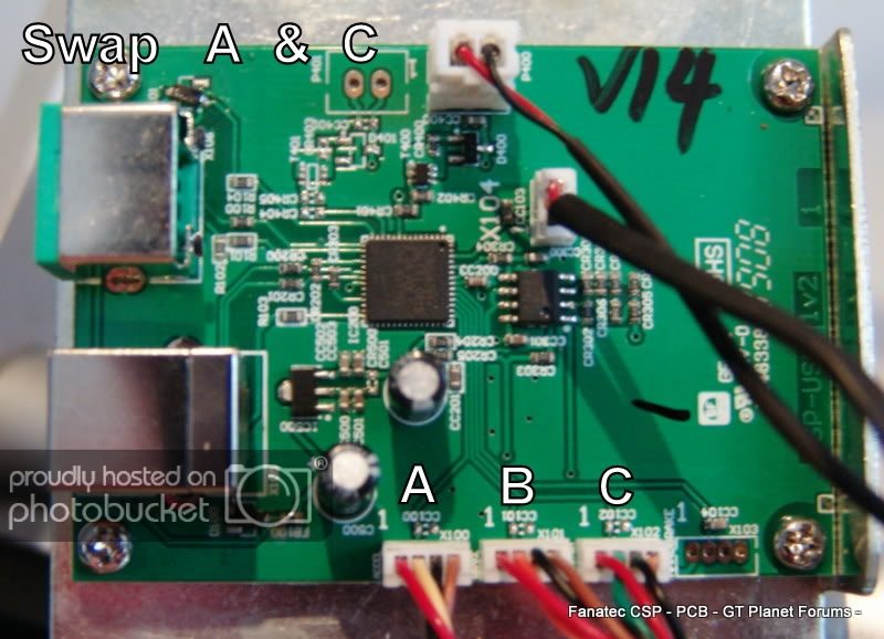
I have made a small picture to show you the problem.

which way do I have to plug in the connector?
Black/Red/White like shown in the picture or the opposit way White/Red/Black ?
Ahhhh... I see. Did the little housing around the pins come off of your PCB, or did it just not have one?
.
Housing? There was no housing, is it important?
It's on the end of your plug shown in the picture above.