- 1,092

- Pierrefonds (Montreal), QC
- pilmat
- pilmat
In an overflow from a thread on brake thoughts (LINK) I decided to try building a hydraulic brake to test it's merits.
The theories are borrowed from MANY places and I take no credit for inovation here, I'm just sharing the experience so we can all learn something together")
Theory being tested: pressure based braking system provides the best feel for simulation braking.
I make no claim to knowing this to be right or wrong, but I want to see for myself.
Goal: build a hydraulic braking system based on simplicity, and to the best extent of reasonable cost.
I'm privelidged here as I work in a speed shop, I have easy access to everything necessary on the hydraulics side. The rest of the technology is bought from help within the sim world.
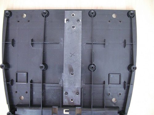
Here is what I've started with:
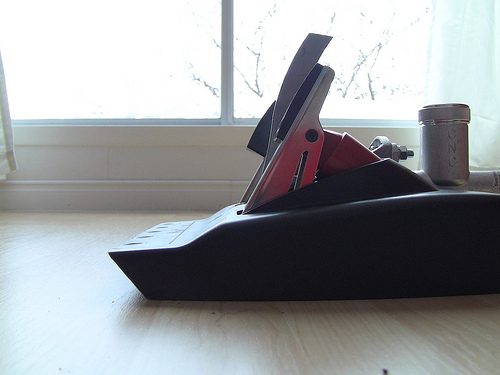
The initial work will be fitting the brake pedal within the G27 environment. Then modifying it to achieve a compatible height. Basically cutting off the end of the pedal and welding a pad back on (I use DSD pedal pads on my current G27 pedals).
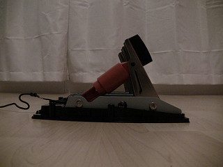
Why G27 pedals? I have a Human Racing GT Chassis which mates perfectly with the pedals, so I would like to keep with what looks good
More info to follow, with pictures
The theories are borrowed from MANY places and I take no credit for inovation here, I'm just sharing the experience so we can all learn something together
Theory being tested: pressure based braking system provides the best feel for simulation braking.
I make no claim to knowing this to be right or wrong, but I want to see for myself.
Goal: build a hydraulic braking system based on simplicity, and to the best extent of reasonable cost.
I'm privelidged here as I work in a speed shop, I have easy access to everything necessary on the hydraulics side. The rest of the technology is bought from help within the sim world.
Here is what I've started with:
- G27 pedals, completely stock apart from the lobotomy.
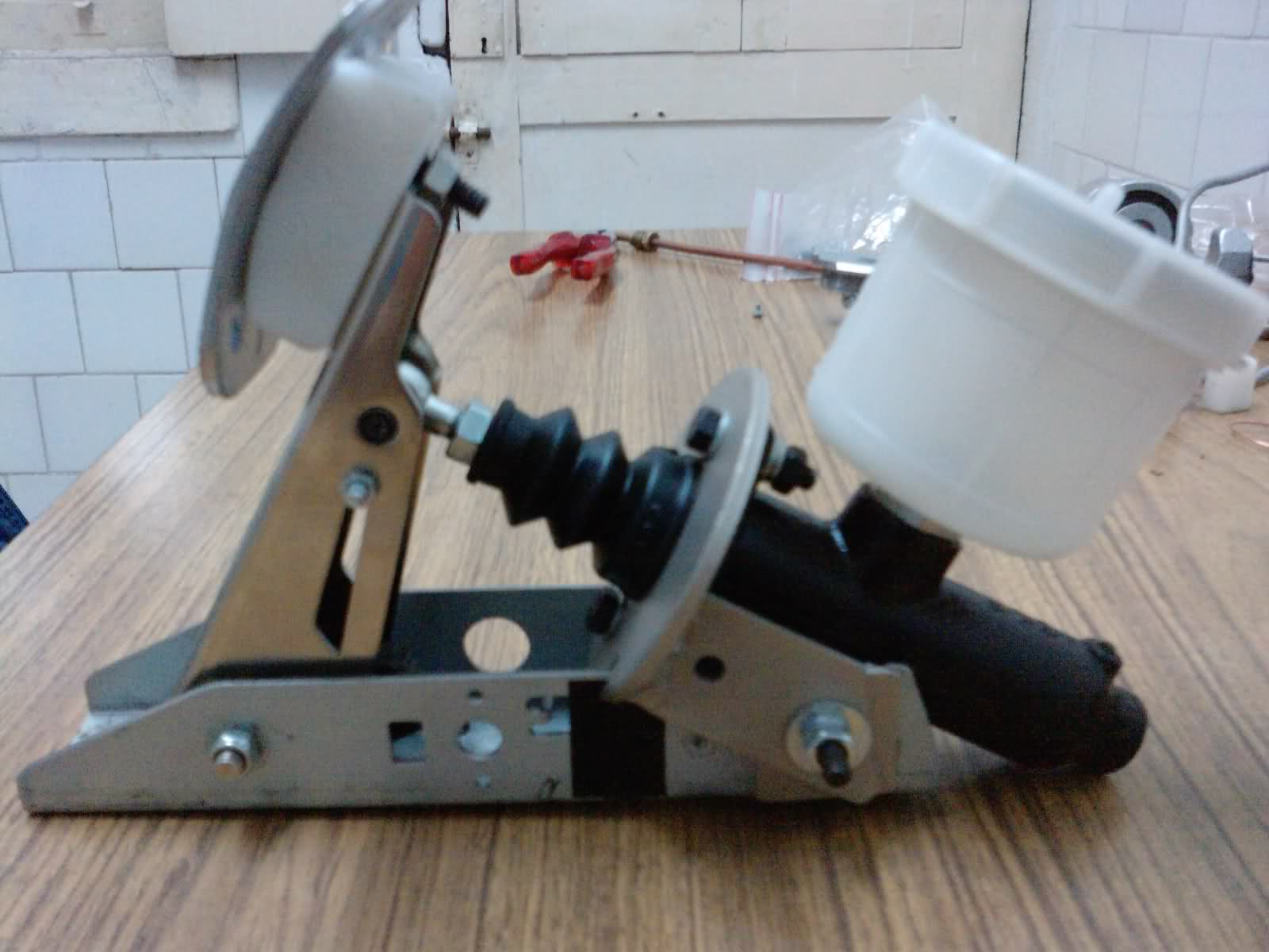
- CNC 340SBU clutch kit (10.25" pedal @ 5.2:1 ratio, 3/4" bore master cylinder and 7/8" bore pull type slave cylinder).
- mV pressure transducer.
- DSD 12 bit controller w/ integrated load cell amp.

The initial work will be fitting the brake pedal within the G27 environment. Then modifying it to achieve a compatible height. Basically cutting off the end of the pedal and welding a pad back on (I use DSD pedal pads on my current G27 pedals).
Why G27 pedals? I have a Human Racing GT Chassis which mates perfectly with the pedals, so I would like to keep with what looks good

More info to follow, with pictures
Last edited:
 ):
):


 ).
).


 It's amazing what force a foot can generate in a panic situation (like braking too deep into a corner in a sim

 . What do you mean?