Ah ok, I see what you're trying to say. First of all, I don't have any measurements, and my motor is already installed and working so no chance of measuring it... But I'll try and help with references to the photos I took when I attempted the fix.
View attachment 1004848 View attachment 1004847 (lvl 9000 ms paint

)
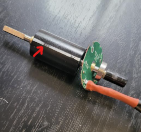
I didn't think you could move the brash bushings (1), and even if it is, it's unlikely that you moved them by accident, as there's no force applied to them at any point during the disassembly. If you are positive that you moved them, then maybe the photos above could serve as some sort of reference for moving them back to the correct place.
If not, then we come to the positioning of the black magnet cylinder. As you can see in the second photo, it should sit equidistantly to the silver cylinder thingies (2), so that the distances A and B are roughly equal. This will ensure, (assuming that 1 was not moved, or you managed to put it back in place), that the magnet is sitting at the right place in the motor.
If you've put everything back together, and the motor is turning freely, that means that the ball bearings and the cover are aligned properly. If at this point the hall sensor magnet is sitting a few mm further than it used to be, that is fine, mine was the same but the wheel is working perfectly ok. If it is more than a few mm, then it is possible to remove the black plastic that holds the hall sensor magnet (but carefully because it is glued, and it's very easy to break), and glue it back a few mm higher so it sits closer to the pcb.


 ... without any new hints about the problem, it doesnt make sense
 . I started my repairing journey recently and hope my wheel base will be fixed soon, but I found some facts that let me struggle ...
 )
)