Build-a-pod (plans inside)

  • Thread starter ericleroi
  • 64 comments
  • 147,683 views
Hi,

I've had a few requests for the plans for my racing pod. I did't make any to start with so I've decided to put some together. Hopefully anyone who is interested and who ends up building one will post their progress as well and also any suggestions for improvements along the way.

I'm going to release the plans in several stages as creating these may take some time.

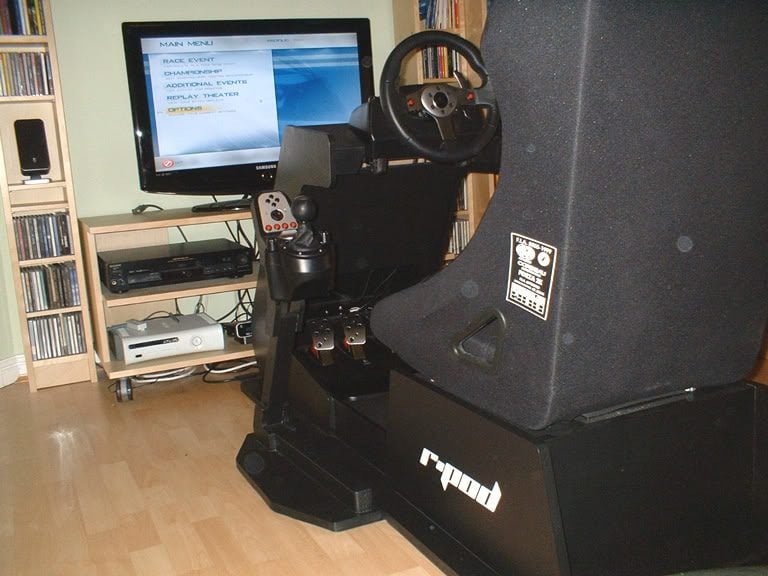
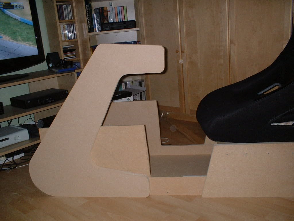
So if you want to build one of these ....

PodBlack001.jpg


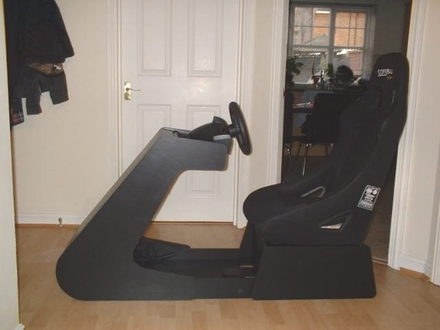
... I'll do my best to show you how.

Any questions or suggestions, just ask.
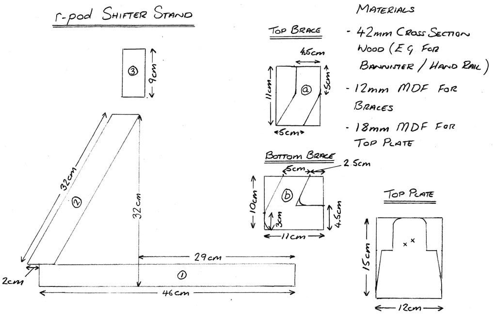
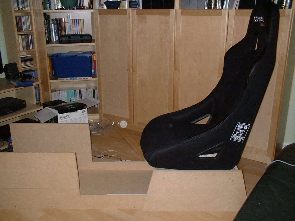
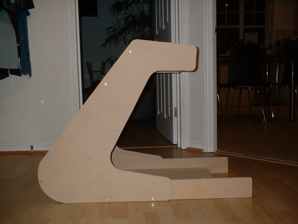
Part 1 - Base unit.

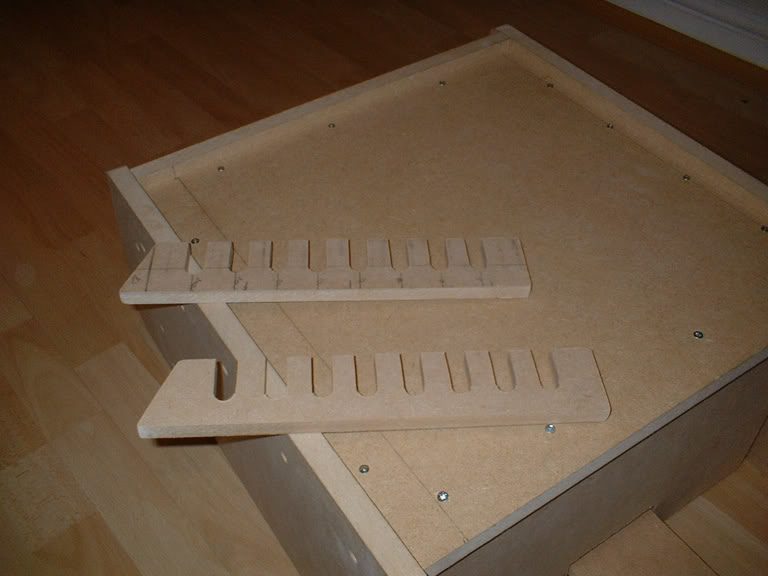
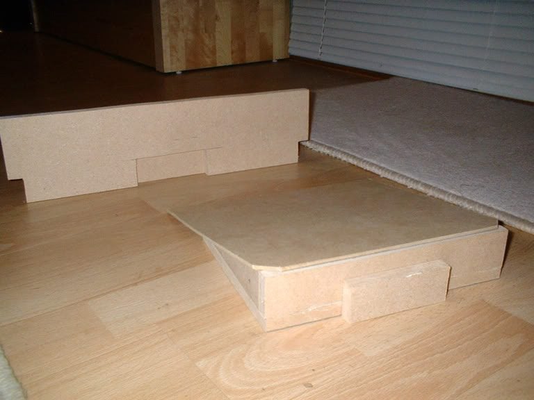
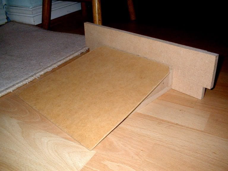
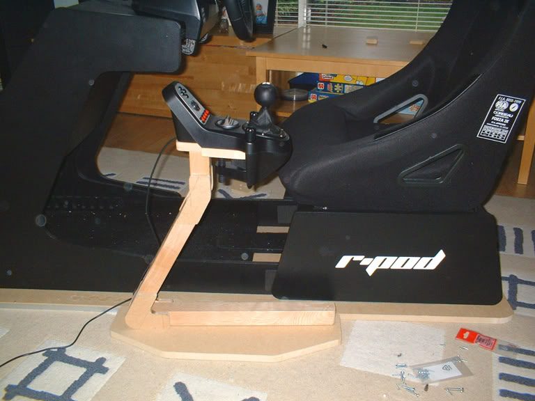
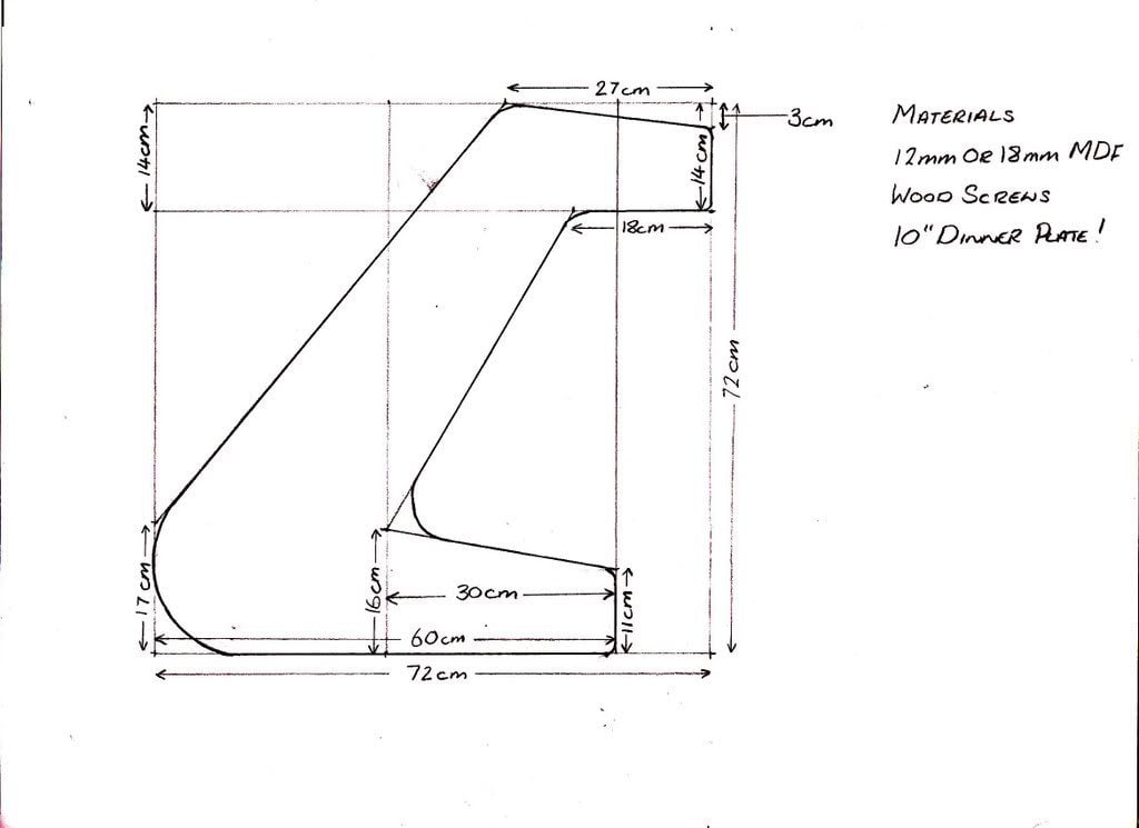
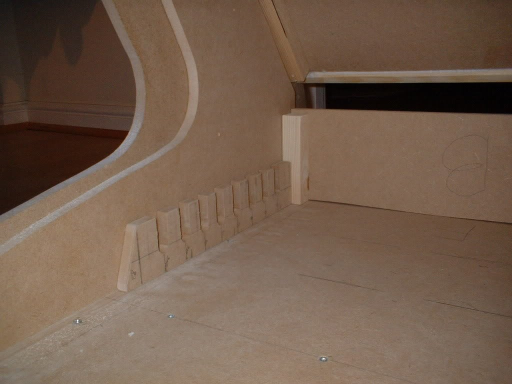
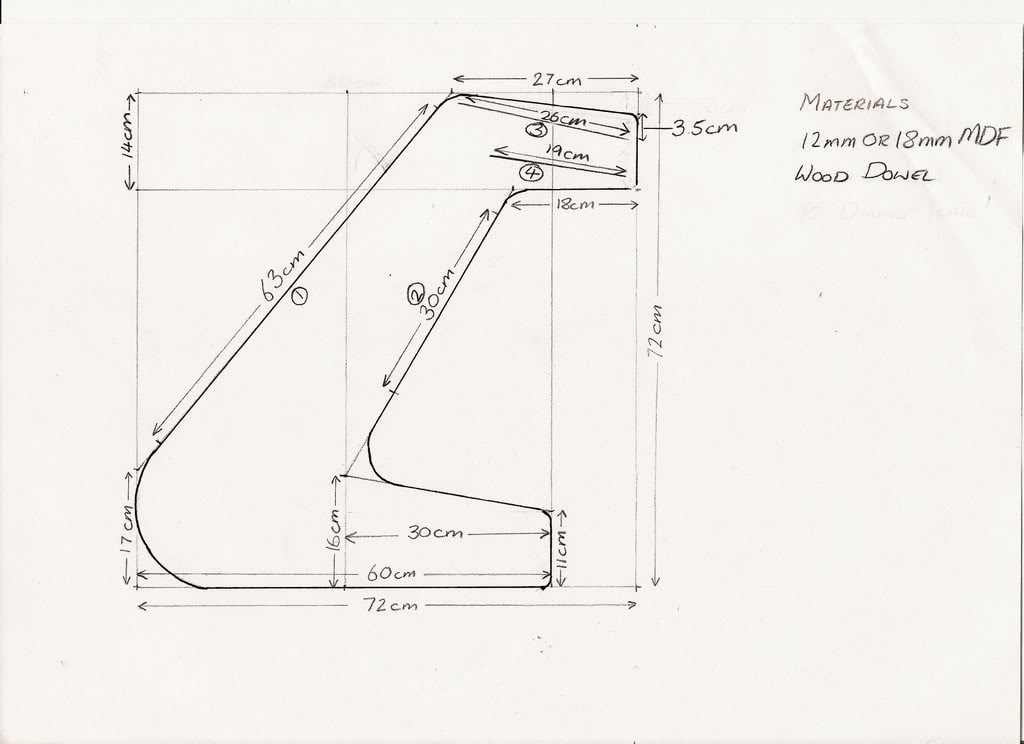
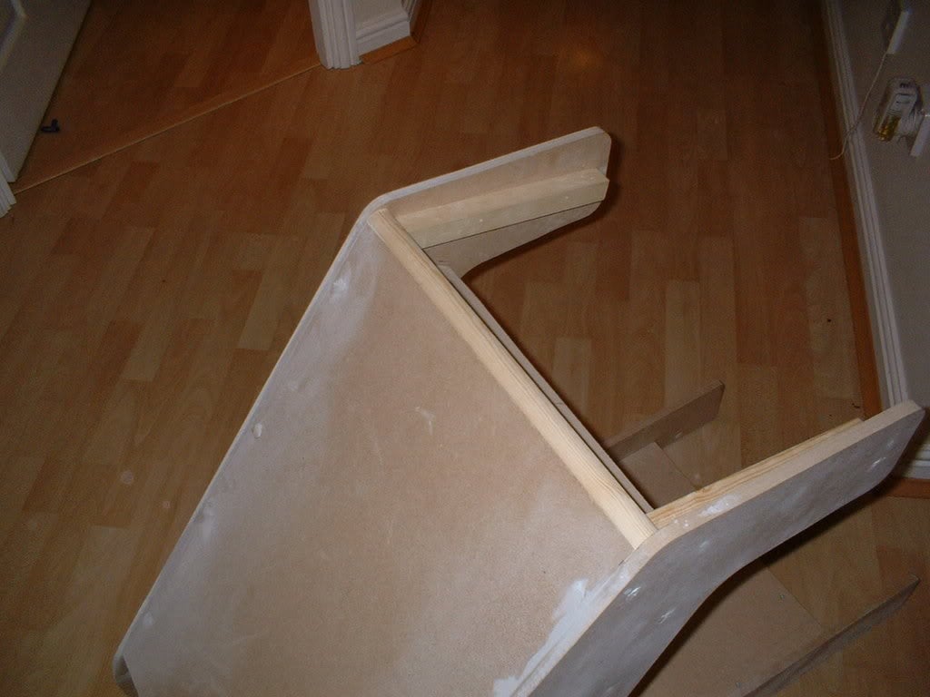
It's important that the base is very sturdy so I've constructed this out of 18mm MDF. I am suggesting a improvement to my original design in these plans. The front section of the base doesn't really require the complexity of the 'tongue and groove' system I used. This I think will be a much neater and simpler option.

PlanBaseUnit1.jpg


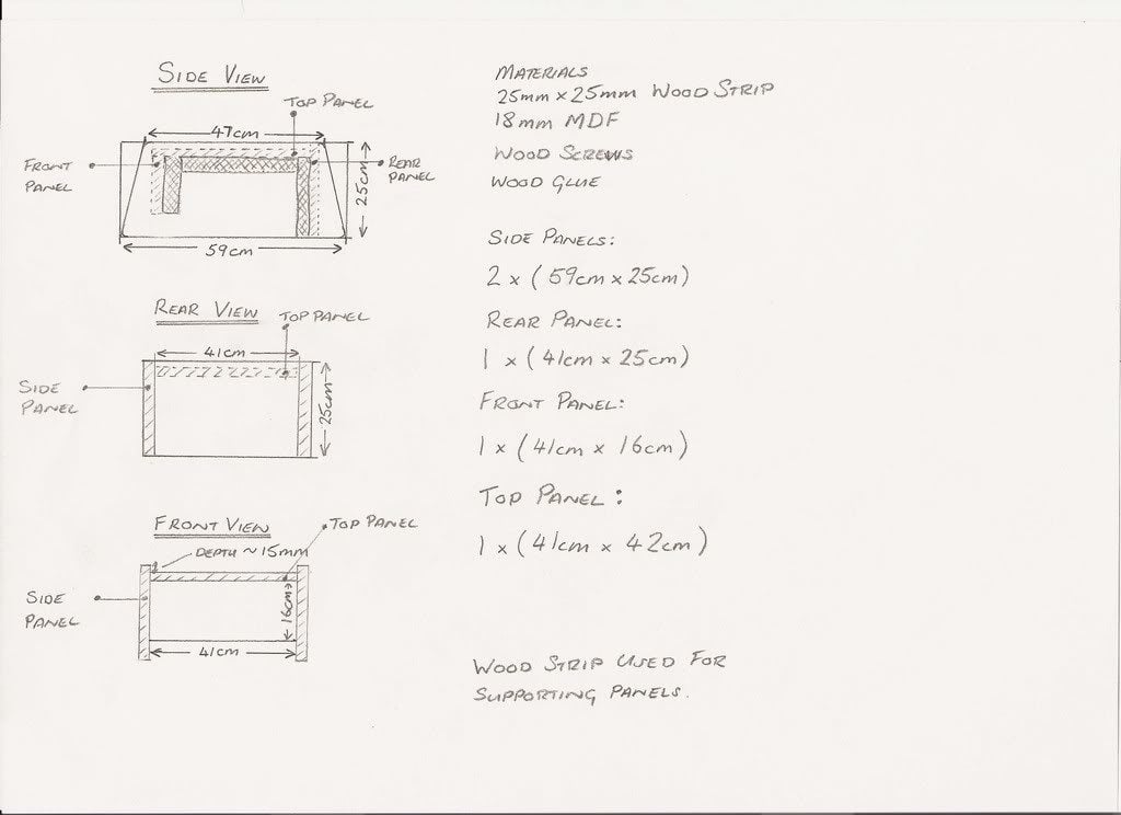
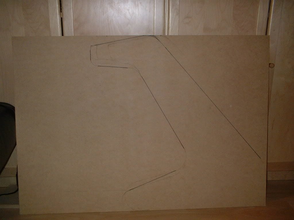
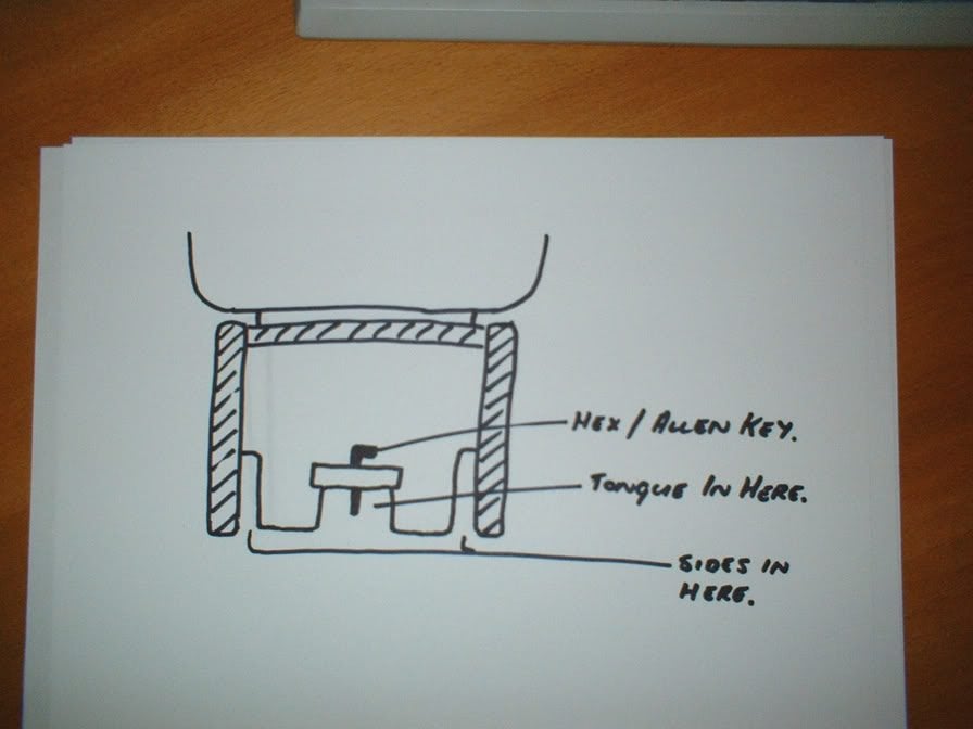
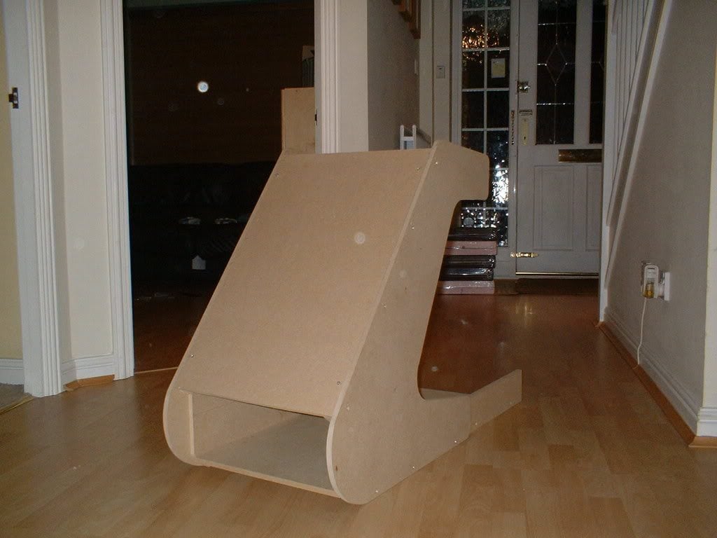
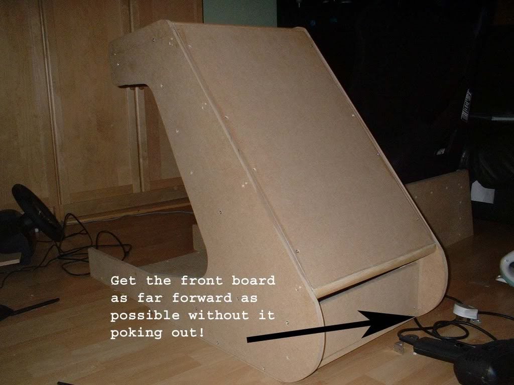
This picture may clarify the plans further.

basecoat.jpg


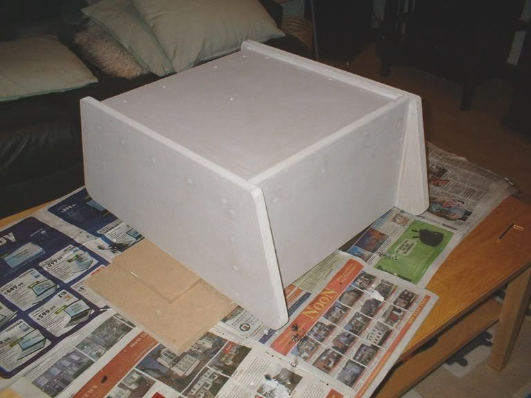
If the plans are confusing in any way, please let me know.

Suggestions:

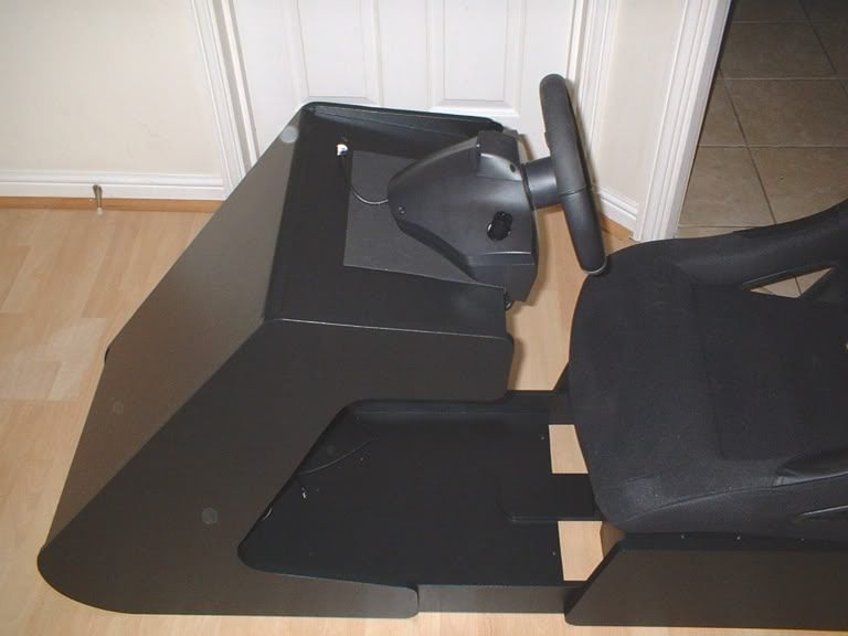
1. Consider the seat you are going to use and whether the dimensions are suitable.

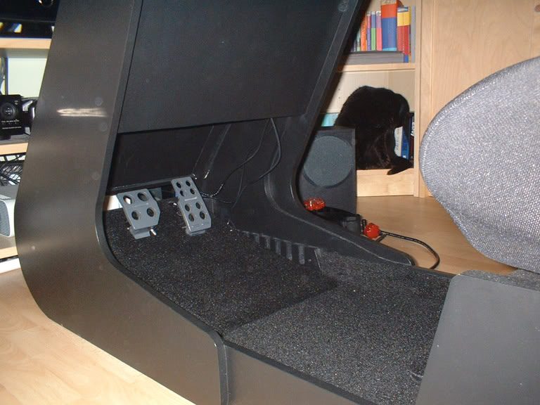
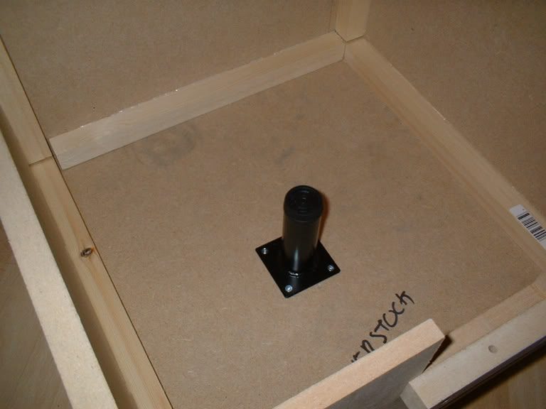
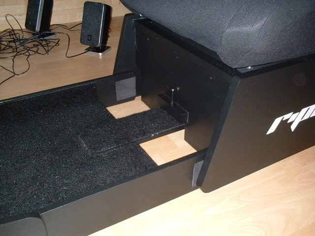
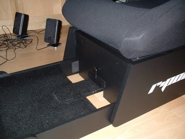
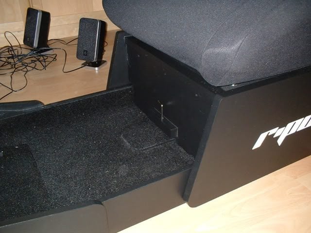
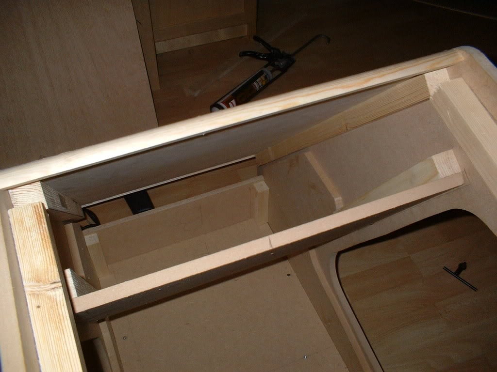
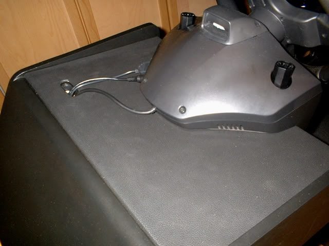
2. Are you going to attach a Buttkicker? You may want to think about how to mount it. I cut out a hole and ended up attaching a small table leg to directly to the bottom of the seat. The following image shows the leg which I originally attached to the base. The effect wasn't enough, so I cut out the hole and bolted the leg to the bottom of the seat. I then blew my amp so am now going to buy a mini LFE, but that's another story.

Kickermount-1.jpg


I'm also running the same thread on another website.
 
Here's a plan for part of the nose section. I had intended to get further than this but making the plan provrd more time consuming than I thought. Apologies for the quality of the scan.

Side plan of the nose section:

PlanSide.jpg


You may want to create a template first:

RacingPod004-1.jpg


Here's a picture of the cut panel leaning against the footwell.

RacingPod007-1.jpg


Considerations / Suggestions:

1. Make and assemble the seat base fist. This will determine whether the dimensions of this section are right for you. Several people of varying shapes and sizes have used my pod and these dimensions seem to be ok for them although things may be different for you.

2. I would suggest waiting until you have completed the foot well before starting on this section. It will give you a better idea of the fit as your feet and the pedals will be raised off the ground.

3. Use a 10" dinner plate to get the curve at the front of the pod. You can use cups and other kitchen items to get the curves right between the other angles.
 
Ok, time for the third installment. This part will concentrate on building the footwell. As mentioned in the previous post, I used 12mm MDF so it was lighter and more transportable. The whole section is pretty stable but I would recommend using 18mm MDF if you are not going to move it around; no point in using a thiner material unnecessarily. The seemingly odd cut at the side allows for doubling up on the thickness which further improves the sturdiness on the design. When the nose section is assembled, you will see how we can improve things still further by overlapping the two sections.

Footwell plans:

PlansFootwell.jpg


*** Correction to above, Front Board should be the same width as the foot board i.e. 38cm or 36.5cm - sorry!

Once complete, it should look similar to this:

RacingPod003-1.jpg


To give you an idea of how it looks from the inside with everythin assembled:

RacingPod019.jpg


Considerations:

Don't glue everything together just yet, the sides of the panels will need to be cut further. This will be done after the nose section has been completed.

I would be inclined to not attach the front panel of the seat base just yet. This section will need to ensure that the footwell section can slide underneath unobstructed and will need modifying to do so. This diagram may help to explain (ignore the 'tongue in here' bit, it's the 'sides in here' bit we're interested in):

CockpitView015.jpg


I have used a length of 100cm fo the footwell. You may be able to get away with slightly less than this. The footwell retracts under the base of the seat for adjustability. Here are some pictures to show how this works (please ignore the 'tongue' setup here, the new design used will be much cleaner. If I'm honest, this was to make up for a mistake where I inadvertantly sawed of more than I should have! looks good anyway though).

CockpitView011.jpg


CockpitView012.jpg


CockpitView013.jpg


Is anybody finding this thread useful?
 
Wow, for a DYI that looks great! +1 rep (if there still was a reputation system). 👍

I might be able to save myself $1000 and make this instead. But, time and money... time>money.
 
Nice blue prints. :) I bet you going to save people a lot of money.
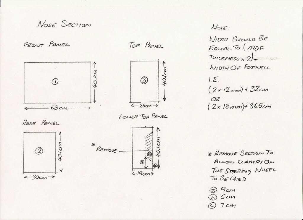
Yeah Time>Money
But we have one more year till FULL release of GT5
 
Thanks for the comments peeps!

Right, here's the last main entry, I guess anything further will focus on cosmetic and general finishing.

One thing to mention first. It goes without saying that any pair of panels (base sides, nose section and footwell) should be cut at the same time to ensure they match.

This section will complete the build of the nose section and only 4 panels are required to do this. Here's the plan:

Noseplans1.jpg


The panels 1,2,3 and 4 attach in the positions shown in this plan:

NosePlan2.jpg


The next step will be to overlap the side sections with the footwell. Wood strip will be used to attach the panels to (approx 20mm x 20mm cross section will be fine) the front of the nose cone so remember to allow for this. Draw around the nose section onto the front of the side panels on the footwell section. Basically we want to get from this:

RacingPod007-2.jpg


To this:

RacingPod008-1.jpg


To give you an idea of how it will look when attached, this a front view:

RacingPod009-1.jpg


Ok, I hope you are with me so far. Any questions, please ask.

The next step will be to assemble the sides and panels 1 and 3. Once this has been done, the nose can be glued 'n screwed to the front although it may be worthwhile doing a dry run and ensuring you can attach panel 2 before gluing it all together. It's important that the front board of the footwell section is as far forward as it can be without poking outfrom the bottom curve of the nose side panels. This will ensure that you have sufficient leg room in the pod.

Nosealignmentcopy.jpg


Once it's all be attached, it should look something line this from the top:

RacingPod017.jpg


The next things will be to cut a section of wood beading which will glue to the top and bottom of panel 1 at the front of the nose section. Here's a picture with it in place:

RacingPod021.jpg


When it's all completed, it should look like this:

CockpitView001.jpg


Ok, that's it for now, the pod build will be almost complete at this point. I'll follow up with another post soon .....
 
A few final tips to get the pod complete. I'm enclosing a couple of pictures to clarify a few things. On the plans for the nose section I have suggested removing a section from the lower top panel. This picture shows this in more detail and how I've finished off the 'dashboard'.

Finish1.jpg


If yout wheel has cables which don't attach underneath the base, you may also want to cut a hole for them. If you're going to use a g25 only, you could consider removing a smaller piece of the top panel so you can hide the wires completely. The cables can then run between panels 3 and 4. I'll almost certainly do this and make another 'leather-look' top to hide the hole for the cables.

PodBlack002-1.jpg
 
Looks great. I am in the process of starting such a build. Your ideas look fantastic. The only thing I'm curious about is how you are mounting the pedals? I saw your pic showing the inside of the nose, with some grooves cut out. Is this to allow the pedal angle to be adjustable?

Any more pictures of the inside of the nose?


;)
 
The slotted sections may be worthwhile making but it depends on how you're going to use your pedals. Essentially it provides an adjustable backboard for any set of pedals to push up against. It's fairly basic in principle but works well.

I'll run you through the process of making them and then you can decide if this will work for you.

First I made the slots to attach to the inside of the pod.

PedalMounts-1.jpg


Then I made the backboard and the pedal stand. You can see a block of wood sticking out of the back of the inclined stand which fits into the hole in the backboard. The backboard fits into the slots on the inside of the pod.

plinth001-1.jpg


plinth002-1.jpg


This is how my modified pedals looked once attached to the pedal base:

P1Complete004-1.jpg


I don't need to use this currently with the g25 pedals as they're fine on the carpet and don't move at all.
 
Thank you.

That was very informative.

I'll probably do something similar, but with a steeper angle on the pedals (can't use pedals at such a low angle, and definitely not flat on the carpet). Or, I'll invert the G25 pedals to an angled board in the nose section.

This has given me a great place to start. 👍


;)
 
Your work is what made me get into a chassis. I was going to build one about 4-5 months ago and came across your design and was amazed at the quality and style (of which was similar to what I had in my head). But after it was all said and done I was unable to construct a cockpit for space constraints, time, money & inconvenience (upon myself/others). I still might do one some day, especially since you have taken a lot of the hard part out of it for me ;). Excellent piece of craftsmanship and design.
 
Thanks for your comments, and glad to be able to help people! I still have some add-ons to the details/plans to post which will include a plinth (easy to construct) and a shifter stand. Here's what they look like before painting:

ShifterMount001.jpg
 
Looks fantastic. Can't wait to see it painted.

I like that you're not just making it functional, but also making an effort to create something pleasing to the eye. Very nice all around. 👍


;)
 
That's a beautiful setup you have there.

Are you going to move your TV up more when your finished. I can't imagine trying to play with the screen down so low.

Is that a Sharp Aquos?


;)
 
Hi there. I think the angle in the picture makes the TV look a little lower than it really is but yes I certainly have considered making a stand for the TV to go on. I even have a design for it! It only needs to be raised about 5'-6" or so to get the horizon fairly realistic. The TV is a Samsumg 32". I'm lucky to have this in a Games Room. I also have a Arcade Cabinet in there which I made a couple of years ago:

Picture30324.jpg


I now have a bar stool for it as well
 
Oh, I see. I almost bought the same set (although a 52"). I placed my order on www.newegg.com. Afterwords I recieved an email saying they were out of that model, but they would give me the Sharp Aquos for the same price. So, I went that route. Still, that Samsung is very attractive.

I'm lovin' that arcade cabinet. What's inside? Nintendo? PC? PS2?


;)
 
It's a PC inside. It runs an Emulator called MAME exclusively so you can play all the old classics; Space Invaders, Galaxians etc as well as a lot of new stuff. The code that is executed is the actual code from the machines so it's 100% faithful. You even have to simulate feeding money into it to get your credits.

I changed and recompiled the source code to get the refresh rate synched to the monitor so everything scrolls nice and smoothly. The monitor is mounted vertically so it's aligned the same way as most of the games I play. There's > 5,000 games now emulated. Check it out!

Very cool. I'd love to do something like that.


;)
 
Ok, here are the plans for the shifter stand. The total height of the design is 46cm.

ShifterMount001.jpg


Please note that due to the way this structure was designed and the width of the material that I happend to use, it is important that the widths of the braces supporting the diagonals are validated. This is best achieved by cutting the pieces, laying them down on the floor and drawing around them. This will ensure that the dimensions are correct. I have done my best to ensure accuracy but dealing with angles and multiple pieces of wood can make taking measurements difficult.

shifterstandplans.jpg


Suggestions/issues:

The height of the stand is built around the height of my seat. You may find that the stand needs to be raised/lowered slightly. This can be done by adjusting the length of section 3.

Once the 15cm x 12cm top plate has been cut, simply insert into the g25 shifter, draw around it then cut with a jigsaw.

I have used 12mm MDF for the braces to give a sleaker look. To attach the braces, I would recommend gluing, leaving it to dry and then securing with screws.

You may want to use thicker wood that the 42mm cross section I have. Mine is pretty stable and the overall stability is really determined by how and to what it is secured. The structure itself doesn't move much at all.

As always, any questions, just ask.

Have fun!!
 
One...Billion...Invisible +reps !...

Nice build, nice guide - Wish I had the room for it !...
 
Thanks for the feedback! If you have any storage, you may be able to build one. I designed it to be portable'ish. The front section can be stored away and the seat/base can be used stand-alone. I'm also going to to put some hooks on the wall in my garage so I can store it away when not in use ..... although I'm not entirely sure when that might be ...
 
Lookin' good. I can't wait to get around to building my cockpit. Your plans will definitely be a good base to work from. Thanks again. 👍


;)
 
Hi, from what I can remember, the price breaks down approx as follows:

Pod and shifter stand - build and paint:

MDF - £30
Wood strip - £10
Beading - £2
Shifter stand wood £7
Paint - £5
Varnish - £6
Screws - £5
Wood Glue - £4

Total £69

Base:

MDF - £8
Foam for the underside of the base - £10
USB extension cable - £3

Total £21


Seat £112
Carpet £8
Leather Vinyl - £5
Custom Vinyl Lettering £10

You could probably get the materials a lot cheaper. I went to a local store which I know is expensive. I also had to buy smaller sheets of MDF due to car carrying restrictions.

If you want any further info, please let me know.
 
Hello,
I thought you may like to know that I used your plans to build a pod for my newly aquired G25.

I would like to thank you for the detail you go into and encourage others to make their own as it is not as hard as I was expecting.

It really is imperative you use the wood strips, at first I thought they were decrotive, as they strengthen the design and trying to screw MDF together dosen't work.

So as not to totally rip off your design I painted mine red.

ps3.jpg


The best of it is that it cost me nothing. We had the MDF sitting in the garage and my girlfriends dad (a joiner) gave me the wood strips. The paint was sitting in the garage as were the screws.

I had so much enjoyment out of making it myself and you plans helped loads.
 
Hey Robie, it's great you had so much fun making it and it looks great! I'm really pleased that you found the plans helpful and thanks for your comments. It is a different experience driving in a purpose-built cockpit as it adds a great deal to the overall enjoyment of the game. Now you've built it you might want to look at using a Buttkicker, I can't recommend these enough. If you've got a PC, you might also want to consider other racing sims like GTR2, GTL, Live for Speed and rFactor. Might as well make full use of all your hard work!
 
I am a big fan of racing sims and will certainly be using my pod for pc games but it is far too heavy to lug upstairs so I will wait till I move house and have a games room for things like this.

The butkicker is a nice idea but it is really one of my aims to do this project for nothing. I think I would also like one either side if I was to do it so that a different one would rumble depending which curb I hit.
 
Back