Clubsport and CSR Elite Pedals Handbrake DIY Info

  • Thread starter mrbasher
  • 44 comments
  • 42,206 views

mrbasher

BasherBoards!
Premium
1,358
United States
Redmond, WA
mrbasherman
Please don't quote this entire block on this topic, it will just make a big mess of things. ;)

I am providing this information to help prevent you from releasing the magic smoke from your expensive equipment. However, what you do with the info that follows is done at your own risk. I take no responsibility for your actions, that is your job.

I have been asked on occasion to provide a cable with which someone can connect a SFA1 or FL2 adapter to the handbrake port on a set of Clubsport or CSR Pedals. I have done this several times now. On one occasion I provided a few cables that would allow a person to use their Fanatec sequential shifter as the handbrake. (digital on/off) As well, I have seen many people ask just what the connector is, etc. There seems to be some mystery surrounding just what the handbrake port on the PCB can do... As well, not every CSP PCB has this port... So before you get your hopes up, you should check.

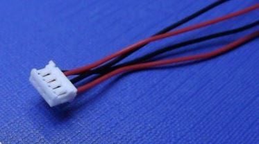
Well, the connector that fits is called a JST ZH style. These can be purchased very cheaply, along with the crimp terminals that go in the plug. The problem lies in the necessity for a tool to crimp the terminals onto the wires. This tool is at minimum, $54 US. That makes for a pretty expensive cable for a DIY project.

I am going to put more details in here as I go along, but for now I will go over some of the basics.

What does the port do?

I have seen some misinformation about this board that needs clearing up...

The handbrake port is recognized as ANALOG in the Forza series of games. So if you connect a pot to the handbrake port and turn it, the handbrake is variable from 0 to 100 percent.

The handbrake port is recognized by Windows. However, it does not show up on the Fanatec properties page. This does not matter... If you go into a game, you can map it to something.

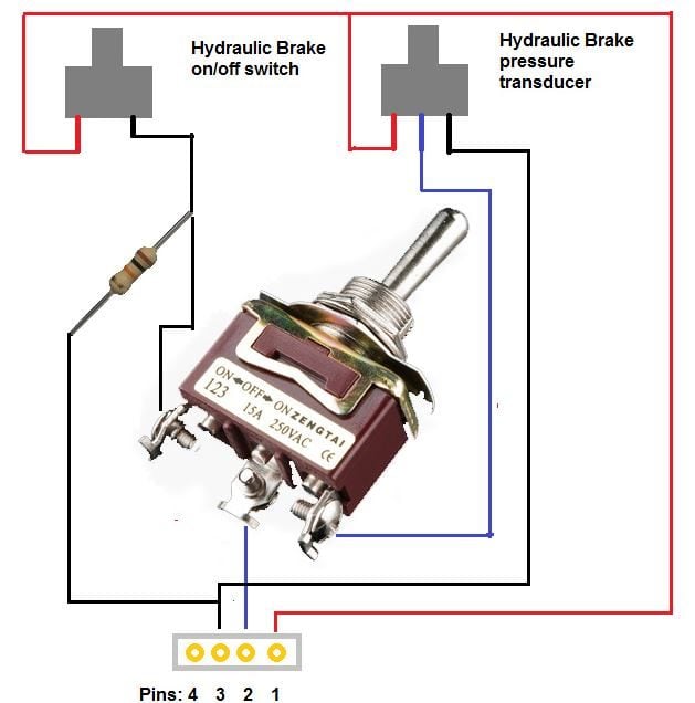
Connector - (plugs into board):

Rather than bothering with giving you the model number of the connector, etc. Pre-made cable assemblies with connectors attached are available via Ebay, just search for JST ZH 4 and you will find some. You need 4 pin connectors! I will search for some others places.

jst-zhr-4.jpg


Connector on the CSP Board:
(not my photo, just grabbed from google and added the pin numbers for reference)
csp_pcb.jpg


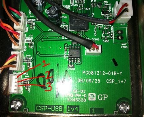
The pin connections are as such:
1 - Positive 3.3v
2 - Signal into the board
3 - Ground
Leave the 4th pin disconnected...

The handbrake port reads an increase in voltage on pin 3 as an increase in handbrake level. This is different from the other ports on the board. For example, if you connected pin 1 directly to pin 2, that would give 100% handbrake.

Examples:
(using quotes on these just for the sake of separation)

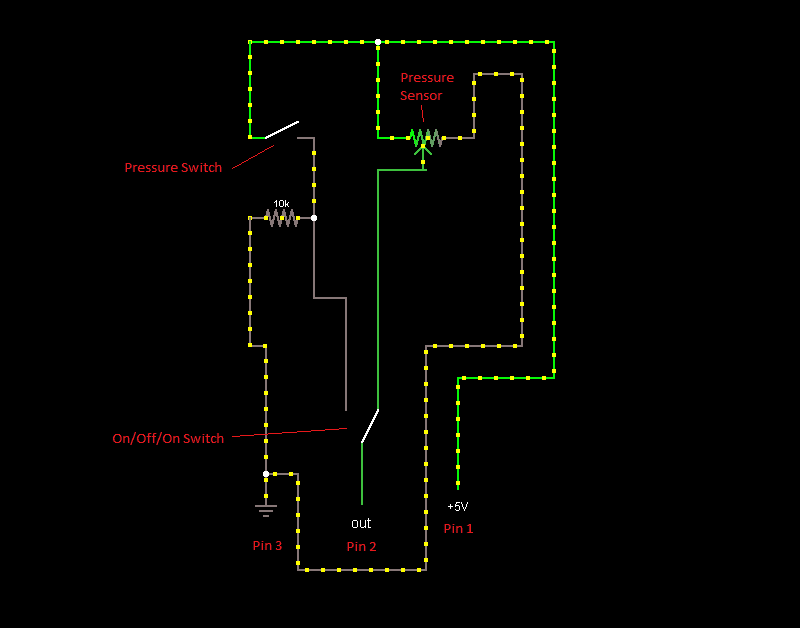
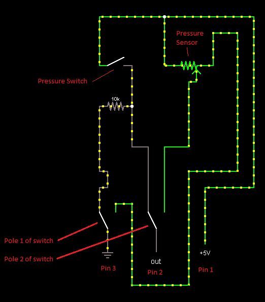
Hydaulic handbrake example - (sourcing the handbrake, master cylinder, slave cylinder and lines are your choice. Derek Speare has posted several examples that can be found on ebay)

This is probably one of the simplest to accomplish as everything can be purchased ready-made. You just need to find the parts and put it together. The hardest part for someone will probably be not making a mess when bleeding the brake lines.

Here is an example handbrake: http://www.ebay.com/itm/HYDRAULIC-H...-DRIFT-HORIZONTAL-VERTICAL-BLUE-/261085921723

Example slave cylinder (pull type): http://www.ebay.com/itm/Wilwood-Pull-type-Slave-Cylinder-NEW-260-1333-/390562921899

Skate board bushings can be used on the slave cylinder. You choose the hardness to select how hard the brake is to pull.

This type of sensor should work for this: http://www.ebay.com/itm/Pressure-transducer-or-sender-500-psi-for-oil-fuel-air-/250988155990 However, I am not positive on the pressures involved, the one linked is 500 psi. It will not matter TOO much as the CSP board automatically calibrates it's minimum and maximum. Transducers of other PSI ratings can be found here: http://stores.ebay.com/Industrial-stuffs/Pressure-Transducer-/_i.html?_fsub=2911276017

Wiring... Copied directly from the ebay page:
Red: +5V. Black (yellow): ground. Blue (green): signal output.

3.3v from the PCB should still work for this fine as the sensor just acts as a pot. Attach pin 1 on the board to the Red wire on the sensor. Attach pin 2 on the board to the (blue/green) wire. Attach pin 3 on the board to the (black/yellow) wire.

I highly recommend soldering any connections you make and using heat shrink tubing to protect them. Remember, put the tubing over the wire unshrunk BEFORE you solder. ;)


More info to follow, I just wanted to get this up here as a start... I will edit to add more later. The format of the above is probably subject to change as I add info as well. I may end up moving this to my website later.
 
Last edited:
Very nice. I never knew the handbrake connector was detected by windows I thought a driver update was required so that always stopped me from bothering to finish my handbrake.

Now the next step is figuring out a good way to connect the potentiometer to my s2000 handbrake.
 
Very nice. I never knew the handbrake connector was detected by windows I thought a driver update was required so that always stopped me from bothering to finish my handbrake.

Now the next step is figuring out a good way to connect the potentiometer to my s2000 handbrake.

Yep :) If you use a program like Logitech's diview, you will see the axis listed there and can watch it move around.
 
I'm trying to order from that site and get this error message when registering. "Your Telephone Number must contain a minimum of 3 characters." There isn't a line for phone number though.

http://www.ebay.com/itm/Mini-Micro-...389?pt=LH_DefaultDomain_0&hash=item2a2ab3134d

Is this the right cable?

Don't order from that site. I removed it from the OP. I didn't realize it was Singapore only or something.

The ebay listing you linked is exactly what you want. :D Wow, 10 sets! Pass them out as stocking stuffers lol
 
Don't order from that site. I removed it from the OP. I didn't realize it was Singapore only or something.

The ebay listing you linked is exactly what you want. :D Wow, 10 sets! Pass them out as stocking stuffers lol

Awesome, now I can make 10 handbrakes lol.

Do you have recommendation on what potentiometer range to use? What do the pedals use?
 
Also any hydraulic brake light switch would do, which just means connecting leads 1 and 2. At least in theory from what you're saying, Basher. ;)

Demon-Tweeks: http://www.demon-tweeks.co.uk/motor...ies/demon-tweeks-hydraulic-brake-light-switch


Also for anyone who starts on hydraulic gear. There are a LOT of different types of screw thread for these systems, with either a convex or concave end on them. So be sure to match your piping and our steelbraided hose fittings to match. ;)
Also for piping you will need a flaring tool like a "Midlock 7203 (imperial)" or "Midlock 7204 (metric)". Mine was around 70 euros I think, bought in a local car parts shop.
 
The switch should work but I think that would only be ON/OFF... Though I'm not sure. Since the input on the CSP will accept the full range analog signal, it would seem a better idea to use it. :)

I will be adding an on/off switch example as well. It's not as simple as connecting pin 1 to pin 2 (on the CSP)

Hrm... here I thought it would be. Or at least pin 1 and 3.
Cause what happens instead of having (basically) a potmeter in between that goes from 0 to 5V, this switch would either just let the 5V through or not (hence its named a switch).

I have one of these kind of switches here, which I wanted to eventually make switchable (with an ON/OFF/ON toggle switch) between an analog pressure transducer and that switch. This so I can use it however I wanted to on a per game basis.

You are correct and it would technically work, but there is a catch which I had planned on outlining in the OP example when it's posted:

You need to place a pull-down resistor (10K should work fine) between pin 2 (signal) and pin 3 (ground) when using a switch type circuit. The reason for this is that if left "floating", pin 2 is subject to all manner of noise, etc. It's floating until the switch is closed and not guaranteed to be at 0 at rest. Placing a pull-down resistor between it and ground ensures this. :)

I did this for someone hear that asked me to make them a cable to make their Fanatec sequential shifter act as the handbrake. There's slightly more to that one as well and I will explain it when the time comes.

So in your circuit with the on/off/on switch, you will want to cut the pull-down stuff out completely when it's switched off. Otherwise it will cause issues with your pot measurements.
 
I made my Fana-Sequential shifter an on/off handbrake long ago by wiring to the B button. It's nice for rally where a quick/brief yank is all you do at times. This was back before I had the Elite wheel and CSV2 pedals. I have to find the time (hard) but I plan to use an affordable drift hydro e-brake, hall sensor (~2 dollars) and wire into the CSV2 pedals to have a continuously adjustable e-brake. You can mount those like on a normal sports car, or vertically near the steering wheel as some of the local drifters do by me. At times I will just on/off yank it anyway though.
 
You are correct and it would technically work, but there is a catch which I had planned on outlining in the OP example when it's posted:

You need to place a pull-down resistor (10K should work fine) between pin 2 (signal) and pin 3 (ground) when using a switch type circuit. The reason for this is that if left "floating", pin 2 is subject to all manner of noise, etc. It's floating until the switch is closed and not guaranteed to be at 0 at rest. Placing a pull-down resistor between it and ground ensures this. :)

I did this for someone hear that asked me to make them a cable to make their Fanatec sequential shifter act as the handbrake. There's slightly more to that one as well and I will explain it when the time comes.

So in your circuit with the on/off/on switch, you will want to cut the pull-down stuff out completely when it's switched off. Otherwise it will cause issues with your pot measurements.

So something like this I guess?
I guess it would be the same if I did this on my Arduino Uno board.

 
Logi,

That won't work. Ideally you would use a 2P2T switch (dual pole, dual throw) and completely separate the two sensors depending on the state of the switch.. BUT... This would probably work if you had to use it (it meaning, the switch you pictured):

34y3ga1.png
 
Last edited:
Logi,

That won't work. Ideally you would use a 2P2T switch (dual pole, dual throw) and completely separate the two sensors depending on the state of the switch.. BUT... This would probably work if you had to use it (it meaning, the switch you pictured):

34y3ga1.png

How's that one different from what I drew?

Oh and I just remembered it's better to just pick a 1P2T (On/On toggle switch).

The reason I don't use a 2P2T is because I don't want any conflicting inputs into the logic of the circuit board. Using 2P2T would mean that both the pressure switch and the pressure transducer would send a signal into the board, meaning it would always send 5V and thus cancelling out the transducer's work.

Anyways, I am taking over your thread with this stuff. Sorry :scared:
 
Logi, it's not problem. That's what the thread is for :)

There are a few differences in the circuit I posted and yours. Take a look again, here is your drawing modified to match the circuit I posted. Remember the pin order: 1 3.3v, 2 Singal, 3 Ground

29ge7vr.jpg


As for the 2P2T switch. What you'd do there is switch ground and signal... If you'd like I can draw that for you.
 
Logi, it's not problem. That's what the thread is for :)

There are a few differences in the circuit I posted and yours. Take a look again, here is your drawing modified to match the circuit I posted. Remember the pin order: 1 3.3v, 2 Singal, 3 Ground

As for the 2P2T switch. What you'd do there is switch ground and signal... If you'd like I can draw that for you.

Ah, I totally missed that. Well, it must be bed time at 5am for a reason. lol

Ground and signal? I can see how it needs to wire up. Though I think I would love to hear (as an electrics newbie) the reason for doing this, feel free to draw it up to explain it clearly for the rest too though.
 
Here is it switching the ground and signal:
soxzbk.jpg


The reason for this is that is removes the pull-down resistor from the circuit when it's not being used. While it only has a slight impact on how the circuit works, it's best to just remove it from the circuit. You'd think it's already removed without doing this, but it's not. The reason is that if both the transducer and switch are connected to the brake line, at a certain point, the pressure switch will activate, connecting the + half of the pressure transducer to the pull-down. This increases the resistance of that half of the transducer. (think of the transducer like a pot)

All that said... It's really not worth the effort in this case to use a 2P2T switch. They cost quite a bit more anyhow and it increases the complexity. Just use the circuit I redid (on your drawing). The worst that would happen is you may have slightly non-linear output from the handbrake.
 
Last edited:
Now that there is a cheap source of load cells how do you wire those for handbrake usage?

I have a better idea for you, if you want to make a handbrake using a load cell... :)

First off, using a real load cell is ideal due to linearity. This little guy seems like it would do the trick nicely: http://www.robotshop.com/productinfo.aspx?pc=RB-Phi-120&lang=en-US

Then you need a load cell amp. You can get one from Derek Speare or Leo Bodnar. I don't think Leo has them in stock right now... So DSD ;)

You need the connectors I listed previously of course, they can be found on ebay.

There is one catch to this... I believe the handbrake input on the board is "inverted" Though I have a fix for that as well. (no, it's not simply reversing the wires)

I will double check that this weekend and post up the info on how to do this using either a stain gauge from a scale (like those on the clubsports) or the linked load cell. :)
 
I already built the handbrake setup with the half bridge at the end so I look forward to your guide for wiring that.

I looked at DSD's page and $27 plus a 3 week wait doesn't excite me. I think I will try using the ad620 as amp.
 
I see. Well if you have the facilities to get set up using that instrumentation amp, there's no reason to buy one premade :)

Here's all you need to do:

a28b553b1069.gif


In the above:
R1 and R2 should be 1K resistors
The strain gauge replaces R3 and R4

In order to determine how to wire the strain gauge, do the following with a multi-meter:

Measure the resistance between two of the wires on the strain gauge.
- If the resistance is 2k, you have found the "outer" two wires. The wire you are not touching is the "center wire." This corresponds to the point where R3 and R4 above meet. This wire will connect to the + (input) on your ad620.

- If the resistance is 1K, try another combination of leads to wires until you get a reading of 2K, then see above ^^^.

Vex in the drawing above is just the incoming voltage to the strain gauge. Vo is the voltage going out to the ad620.

When I have a moment I will draw the wiring diagram, that will be much simpler to follow. You should be able to put all of this on a breadboard without too much trouble.
 

Latest Posts

Back