Well I am only a student and I am just guessing, but there are a few ways I can see of dealing with this... Of course I could be completely wrong, so obviously don't take my word for it!
Also when I say 'hardware', I mean physical electronic components, not just the motor. If you did just add the motor you'd likely blow something important in the wheel up because of excess current gain basically shorting it out.
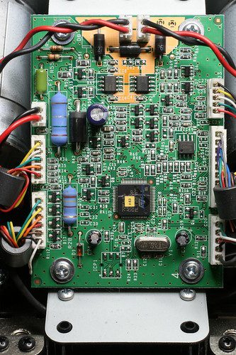
The way I imagine the G27 to work is like this: You have the 5V USB powered logic and 12V externally powered motor circuit, which if I remember correctly runs at 12V 1.25A, or maybe 1.75A, I can't remember exactly. You obviously can't use the 5V signal to drive the motors directly, so as it is there must be a point on the board where 5V is telling the 12V what to do. So it follows that you should be able to hook in to that 5V signal and replace the 12V circuit entirely with a 48V one (for the sake of example), and I'm pretty sure that would be easy enough to do, in theory anyway.
As far as I can tell without an oscilloscope and without ever looking inside a G27, there are two ways Logitech can get varying levels of torque from the wheel as they do, namely pulse width modulation (PWM) or an analogue signal. PWM is a digital method where they basically vary the duty cycle of a rectangular pulse wave, or to put it more simply, it's a digital wave (so it only has two states, on and off) which varies the on and off time to produce the same effects as an analogue signal. My bet would be that this is what they use.
The other option is an analogue signal, which would make much less sense because transistors are difficult to regulate and G27 wheels would need to be re-calibrated every few months as the transistors age, and they'd also change their response as they get hotter from normal use, becoming more conductive as they warm up. I really don't think this is what they've used, though.
It's possible they've used something I don't know about yet, but if they do use PWM you should be able to hook into that signal, add a 48V motor controller to the end of it (which is all hardware) and hook that up to the motor. There are loads of motor controllers you can buy pre-made from robotics hobby sites and some motor controller ICs, like the L293D, should you wish to build your own.
Assuming I guessed right and the motors are controlled by PWM, this might be worth reading, if only for the theory, but it has some examples of the kind of circuit you might need:
http://www.picotech.com/applications/pwm_drivers/
I can't really say anything with any certainty, though, until I've opened a G27 and had a probe around with an oscilloscope and unfortunately my wheel is still very much under warranty so I'm far too scared to use mine as a guinea pig! I do hope that was of some use, though.
")


") to replace them with? Like an RC Car motor or something.
to replace them with? Like an RC Car motor or something.