Fanatec CSW/CSR Elite Modders Thread *UPDATE February 2014*

  • Thread starter eKretz
  • 3,600 comments
  • 584,890 views
Thanks a lot for your advice eKretz,

when I changed the motors the first time I recognized that the drivers below the heatsink were not even and
the gap has been filled by thermal compound which isolates more than taking the heat away.
I expected more precision on a product engineered by a german company......all that glitters is not gold......but the german motors put the record straight! :)

As I did not want to solder on the PCB to put the drivers on one level I decided to match the heatsink´s "landscape" to the level of the drivers by sanding/grinding. Now it is just a touch of thermal compound (bought the right stuff at my computer store) between heatsink and driver to enhance cooling performance. The guy from the computer store
recommended thermal compound patches but I like it old school and I´m sure it performs better.
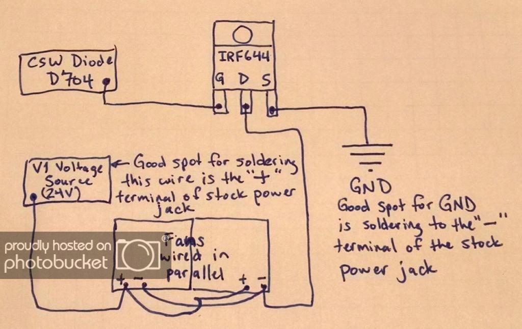
Here´s a drawing:

heatsink.jpg

I also mounted a heatsink on the back, isolated with glimmer/muskovy glass from the PCB to avoid short circuit.
You can see a very slight "bow" in the main heatsink - that´s the grinding I did - not much but now it´s very tight:

heatsink2.jpg


Got the confirmation that my fans are on the way - I hope to post some photos soon.

Happy 1st Advent - it´s below zero here and I´m gonna test out some hot wine punch on
the xmas market. Cheers! :)
 
Last edited:
Max, the center chips that are not at the same height as the FETs are actually just blocking diodes - they don't really need the heat sink - that's why they didn't go to the trouble of making sure the mismatch in height was rectified - so you didn't really need to step the heat sink.

I prefer the thermal compound to the "patches" as well, although I did use one on the back of the board where I also added an extra heat sink. I wanted to use a thermal patch there so as to take advantage of the electrical insulation so I didn't get a short circuit back there like I did the first time (I had attempted to insulate the traces and vias using CA glue, but it apparently didn't isolate them well enough).

Happy holiday! Don't get too crazy with the wine buddy! =)
 
Hello eKretz,

yesterday evening I reassembled my wheel:

17700559.jpg


All I can say after the first rounds on the Nordschleife is: WHOOOOHOOOOO!!!!!!

The wheel really came to life with more details in FFB and massive amounts of torque.
I´m really impressed what a simple motor change can do. Let the torque be with you!

I just took some rounds to test and adjust the FFB roughly in Assetto Corsa so
the longterm stability on endurance races is not tested yet but what I can say
is that after one round Nordschleife the Fanabuchi´s were already weak and
after two more the fan just blew out warm air - right now with air cooling and
some additional fans the wheel is cool and stays cool!

Do you have some settings in Assetto Corsa you prefer? (wheel and ingame)
I´m driving now with the latest driver and firmware - do you have any
other recommendations?


The new PSU is dead quite and the pump (I placed it on a pillow on the ground)
makes some noise but the air coming out the motors is louder than PSU and pump.
This could be annoying when you play without headphones but when I had them
on my head the whistle of the outcoming air was not recognizable anymore when
you start driving.
The whistle sound could be reduced by choosing bigger brass tubes (6mm) which
lead the air into the motors but whith the situation right now I´m more than satisfied.
....maybe another project. :)

Here are some pictures from the cooling:

The fans (40x40x20 mm) cooling the motor cans. I attached a strip of velcro on the
fan top side and put a slice of foam on it. Cable ties are fixing the fans.
I had to cut the bottom fan because the position sensor was too close.

20161211_163248.jpg
20161211_163235.jpg


The cable ties have been put together on the back side which gives a nice fixation
as the zero position pin comes close....very close:

20161211_163208.jpg


I had to throw out the washer of the position pin and did some grinding to pass the fans without touching.


20161211_163642.jpg


Here you see the clearance between fans and the zero position pin:

20161211_163132.jpg


An additional fan (60x60x20 mm) was mounted on the right side (pushing air into the wheel) as well

as on the left side (stock fan, 40x40x10 mm)) which takes away the heat coming out of the motors
and the heat sink. The combination gives a nice cross ventilation.
Here I had to install an "air-guiding" which is just a stiff plastic foil attached between the big fan
and the small one to ensure that the air for the heatsink is not sucked away.
(You can see a slight indication if you look closer)

(The aluminum I took away on the left piece´s bottom was related to a former version
of my air cooling, not necessary with the version I posted already)


20161205_183451.jpg


I also changed the heatsink to a better/bigger one:


20161212_212426.jpg

20161212_212348.jpg


And here´s the test environment:

20161213_105039.jpg
20161213_105011.jpg
20161213_104932.jpg


(BTW the racing seat is selfmade, having a F1 seat as inspiration. Mostly plywood but the wheelstand

is made out of fibreglass, then carbon foiled everything)

Once again:
Thanks for all the tutorials, pictures, thoughts, doubts, comments and enthusiasm
you all put in here. Thank you!

I wish you all a merry christmas and a happy new year!!! :):):)
 
Last edited:
Please Help Me!

I have been through quite a few sets of (Mabuchi) motors during my brief ownership of the CSW V1. Every time I replace these motors, I have calibration issues. The wheel turns clockwise until the stop, reverses, then travels all the way to the other stop.....and stays there - with the belt slipping a little. I've tried wrenching the wheel back to centre, I've tried swapping the motor polarity, I've removed and checked the POS and ZERO sensors...etc.

I suspect the ZERO sensor signal is somehow to blame. I saw somewhere someone said the pin is magnetized. Isn't the sensor just an optical one? If not, perhaps the pin in mine has become de-magnetized.

This is how desperate I'm getting. Each time I have to disassemble the base as it won't calibrate (again) every part gets more worn, scratched...etc. despite my best efforts. I'm on Driver 250 / Firmware 175. I use a Universal Hub and have been told I needed the newer F/W for it to work.

Any one else with continuous problem? Wheel turns clockwise, then anti (counter) clockwise to the stop - and just sits there, motors straining. I'm getting heartily sick of this CSW base. I have pulled the old G25 out of a cupboard to use, and it works perfectly! 10 years old at it still calibrates!!!!

If it wasn't for the fantastic shiny aluminium front piece - I'd get a T500 in a flash!

Simon.
 
@Madmaxxiv - looking good! I'm glad to hear it's working well and that this thread was some help and inspiration to you! I run my wheel with an older firmware so my settings probably won't do you much good. Every firmware seems to slightly alter the feel of the wheel. I haven't even downloaded any of the latest ones, as I'm perfectly happy with mine where it's at.

@Simon Edwards - I will take a closer look at the absolute position sensor and get back to you on some things to test/try. I'm not sure offhand if it's a Hall effect sensor or something different, nor whether that pin is even magnetized - I've never had a problem with mine so far (knock wood!).
 
Thanks eKretz,

Raytac pointed out wheelcheck and the LUT generator for Assetto Corsa (how embarrassing for me to ignore these excellent tools which were already mentioned in this thread!!!).
I made the test on wheelcheck and after the csv file was inserted into the right AC folder the wheel moved from wobble-wobble to a smooth and precise track tool (I´m exaggerating a little bit) - but that really made a difference.

Now the wheel feels not only stronger and more precise due to the motor change but also reacts more detailed on the settings in AC like Kerb effects, enhaced understeer feel and Slip effect.

For those who did not use these tools so far I just can recommend a try on these! Thanks to Raytac at this point.

Cheers,


Martin
 
@Simon Edwards did you do any further diagnosing on your sensor problem? I took a closer look at the absolute position sensor for you and can give you some diagnosis tips. First, hopefully you have at least a multimeter? There are 4 wires going to the sensor - red, black, white and green. With your wheel on after calibration, check the voltage between red and black and make sure you're getting power.

Next monitor the voltage over green and white as the steel pin passes through the sensor - you should see a steady voltage while the pin is not in the sensor and that should drop off when the pin is centered in the sensor blocking the magnetic field. This does appear to be a Hall Effect sensor, but rather than a magnetic pin, it has a small electromagnetic field generated on one side of the sensor that is read on the other side of the sensor. When the steel pin blocks this magnetic field the position is noted by the MCU.

If this is all functioning correctly perhaps your problem lies elsewhere. Let me know what your numbers are after you check it and if you want or need more in-depth help contact me via PM.
 
Merrz Christmas to all Fanatec modders.

I was not using my modded wheel for a long time, started againg few days ago. After changing the original motors with the mod kit with Buhler motors from Eric, after a few days of using, some squeak noise appeared... I wanted to oil the motors with some bearing oil, but did not get any non silicon oil which was not recommended by Eric. I was hoping, that the noise will disappear after some time. But it did not. And what is strange, other sound appeared, when turning the wheel fast...
You can hear it here:


So are these sounds ok or not? If not, what is causing it and how to get rid of it.
 
The squeaking is probably the motor brushes. This happens on stock motors sometimes too. It's usually louder in one direction than the other for whatever reason. It's pretty common with high performance brushes when the motors are turned slow like this - brushed motors aren't designed to run quietly at such low speeds. If you ran the motors at their rated speed there'd be no squeaking - but obviously that doesn't help for our wheels' situation.

There are a couple ways to try to quiet it down - the easiest is to remove the air cooling lines at the back of the base and apply some (NON silicone - you definitely got that right, lol) oil to the inside of the quick release plugs then plug the air lines back in and run the air pump while turning the wheel back and forth for a few minutes. This should get some oil back there and may dampen the vibration that's causing the squeaking.

If you're still having problems after that I can give you a method that will definitely work but I'd rather not post outside of PM as it's a little more involved and does require a bit of finesse.

I'm not sure what your 2nd sound is - I think I hear it - are you asking about the clunking noise when rapidly reversing? That could be any number of things from your screws holding the quick release collar for the steering wheel to the main pulley slipping on the steering shaft.
 
Actually, the short clunking sound you hear Eric is the third one... The second sound I was writing about is a strong chafing sound hearing all the time while turning the shaft quickly... It was not there after installing the mod kit. It appeared later. Regarding the clunking sound, I think, that the pulley is not slipping, I consider it to be maby too stiff, not loose... And what is the third sound?

I will definitely try to get some bearing oil. This sound is the most annoying...
 
Yes it can be very irritating for sure. You should be able to eliminate it with a little bit of tweaking though. If the oil doesn't do the trick PM me and I will try to guide you through the other way.

I'm not sure about the chafing sound - maybe double check your motor belt alignment to be sure you don't have the belt rubbing somewhere. And regarding the pulley being loose - I don't mean the belt tension. The main pulley is held to the center shaft by a threaded collar, or nut, and two dog-point set screws. If these loosen up you can get a little slop and clunking.
 
Hi guys, Solder Jack is back! :)

While cruising around for some time with my air cooled Bühler engines I recognized that the air pump
is producing warm air which heats/warms up the air hose and pushes warm air into the motors.

In the first tests I used the uncut air hose (3m) and the air could cool down on it´s way to the motors.
With my new setup I use a 1m hose and that´s too short for cooling the air down.

The cooler the better and after xmas dinners, lots of finest chocolate and lazyness I had to swing my solder iron again....

for some "steampunk" air cooling:

20161227_153344.jpg
:
20161227_153507.jpg


8mm & 6mm brass pipes were cut, drilled and soldered together, some bent copper wires
for the fan mounting have been attached as well:

20161227_153532.jpg


After installing it in front of the air pump I powered the fan with a variable
PSU (3-12V) so I can adjust the amount of cooling to my needs.
The 80x80mm (12V, 0,13A) fan runs actually on 9V cooling down the air so much, that
the air hose on my wheel does not get warm anymore, it stays cool even after 1 hour of driving.

20161227_153619.jpg


Happy soldering! :)
 
Hey guys, I just picked up a v1.5 base for $30 over on the iRacing forum. It is completely stock, but the fan circuit doesn't work as the fans don't spin up at all. Everything else is fully functional, and the fans do work (I took the base apart and tested them). So my question is, is there any way to fix the board? Or does anyone have an extra board laying around they don't need? Worst case scenario I'll just wire the fans up to external power I guess, but I'd rather not have to do that if I can avoid it.
 
I already PM'ed this to loko, but I guess I'll post it here too. I use this simple circuit to power my fans on at full speed when the wheel is switched on and power them off when the wheel base is switched off. The IRF644 is just a MOSFET I had in my spares bin so that's what I used, it's overkill for this application, but I didn't feel like ordering something else so I used it. There are quite a few other guys running this now also.

IMG_20141011_024532.jpg
 
Hi,
There is a lot of information on here but most of it is a few years old, so forgive me if this question has been covered comprehensively before.

However, what are the options to replace dead motors on a V1 CSW?

I have found a old link in another forum which seems to recommend these motors. However, that post is years old too and the thread never actually mentions the motor names so I am worried the items in the link may have changed?

http://www.ebay.co.uk/itm/2-X-Dunke...PM-/281206768331?_trksid=p2141725.m3641.l6368
 
Hi flibber,

I had multiple failures on my CSW V1. I looked at the Buehler motors (around $50 each, plus shipping) but wasn't prepared to spend over $150 all up. The motors you are looking at were my number 2 choice. They look like good German engineering. One point, though. The shaft on the original motors (and therefore the bore of the pulley) is 3.175mm. The shaft on the Dunkerenmotoren (or whatever) is stated as 3mm. It may be loose.
I looked on ebay for ages - comparing torque, speed, start-up current...etc and found these

http://www.ebay.com.au/itm/DC-12-24...e-DIY-Model-/322446592864?hash=item4b13508b60

Don't worry about the 2900 RPM figure. That's at 12 volts. The motors are rated 12 - 24v so at 24v you can double this number - 5800RPM (no load) I think , from memory, the originals were around 5200RPM so it's a handy upgrade. The torque specs are a little better than stock also. I always worried about going too large with the motors as I don't know what the PCB will take. I already upgraded the heatsink, and ran the base with the perspex top removed. In hindsight I don't think it was necessary.

I have them in my V1 and they're fine. They feel the same as the originals - except a little quicker and they have BALL BEARINGS on the output shaft. That way you can put a realistic amount of tension on the belt without distorting / bending the shaft. This distortion winds up causing drag. This drag caused heat, stiffness, brush arcing...and eventual motor failure. I reckon that's what happened to my original motors. I tightened the belt to a. reduce slippage and b. to realise the more subtle feedback that the motor responds to, but the wheel misses due to this slippage.

They're cheap (AUD$9.99 - free shipping) but they work. I bought four of them. I'm still on the first set. By all means take a good look at the Dunkermotoren. I did. It was the shaft size (and price) that made me look elsewhere.


I hope this helps. (By the way - if you can find a Johnson branded motor of workable specs they went into the Logitech G25/27. They're identical in every way - except they're better quality and last a lot longer.

Cheers. Simon.
 
Hi Simon,
Thats brilliant information, thanks.

Are the motors you linked bigger than the stock motors? i.e you cannot use the stock heat sinks? Do you also have to drill new mount holes?

Also, what is the score with shaft pullies? Do the old ones just pull off the stock motors and push onto the new ones?
 
They're exactly the same size. I found these motors are of the type '555'. This means they're the same size (57 x 35mm from memory) as the originals. They use the same m3 screw on a 23mm(?) spacing. They're pretty much the same motor from the same manufacturer that Fanatec's Chinese partners used.

I tried the next size up (775) and went to all the trouble of grinding down the 5mm shaft (to the 3.175 I needed.) They had WAY too much power. They wouldn't get through the calibration without the unit shutting off. Too much current draw.

There are 545 motors out there - same can size - weaker (12v) internals. The original motor as used in the CSW V1 is a 'Mabuchi RS555-22150'. It's a 10 buck motor and has lead to most of the (many, many) failures. I've had my rant so I won't go there again.

The motors I linked in my previous post mention a round shaft - with no 'flat' for tightening the screw. Surprisingly, mine came with the EXACT flat I needed. If not you can either file a small flat into the shaft - or use some sort of 'lock-tite' ON THE SHAFT. Don't use anything on the grub screws that 'hold' the pulley on. I overtightened mine and stripped the (3mm) thread in an instant. Fortunately I was able to drill a new hole in the pulley, and tap it to 3mm. It wasted a heap of time, though.

Some tips - Take photos of ALL the cabling. If the sensor wires tear off, or one of the ribbon cables break it's great to be able to refer to colour photos.

Be VERY careful with the plastic code wheel. I didn't realise the lines were just printed onto the plastic disc and accidentally rubbed/scratched a few off as I worked on the wheel. Ditto for the sensors (Zero and POS). I broke wires off (they are VERY flimsy) and could never be sure if I put them back the correct way.

Best of luck with everything! If you have any questions - ask. I'm not an expert but I did spend 3 months trying to resurrect a broken one I got off ebay. I got it working in the end - just in time for Fanatec to release the CSL base. It's got the same motor as the V2 for half the price - and my existing Universal Hub fits it.

Good night!
 
Any tips on how to release the grub screws on the pully... mine are tighter than a nun's chuff?

Edit...

Actually figured it out.

1) Gently (but forcefully) prise of the pullys off the motor spindle using a flat screwdriver to lever between the pully and the black bracket.

2) Once the pully is off, wrap it up in tin foil so only the grub screw is showing.

3) Mount the pully on a nail (using the axel hole)

4) hold it under a candle for about a minute until it gets to volcano heat

5) The grub screw then comes out easily.
 
Last edited:
Hi for my Csr Elite wheel, what red and black power cable connected to Mabuchi motor? Please .

I join photo.
 

Attachments

  • IMG_0184.JPG
    IMG_0184.JPG
    85.1 KB · Views: 176
Last edited:
The motors in my CSW v1 are going out the window.

I'm trying to find some instructions on how to replace them. Does anyone have a copy of them?

My main questions is outside of new motors do I need any additional parts?

All the photos from OP are gone so I can't use them.

I've been browsing through the thread and have saved some links to the replacement motors so a least I have that.
 
I have put together a little diagram showing the connections from the Main PCB to the Steering Shaft QR (Quick Release) connector. I suffered from a shredded ribbon connector and stupidly cut all the cables off BEFORE I drew a diagram (or took a photo) showing where they all went. I finally came across a hand-drawn diagram (kudos to ekretz) which got me out of trouble. I have since drawn up a diagram in 'Paint'. It came out accidentally too small but then I figured - hey, it's the perfect size to stick inside the plastic rear housing of my CSW V1. There is no fan on the back of this model. Now I'm covered. Next I'm going to add the colors and pin-outs for the POS. ZERO. and MOTOR connectors. It doesn't take much to break one off when you're concentrating on replacing motor/s or belt/s.
The colors I have put on my diagram are just the ones I used. I'll include the 'blank one as well for people to fill in their own colors (if they want).

As for swapping out the motors, flibber is dead on the money. If you wreck the grub screw/s you're in all sorts of trouble. I did! What should have been a simple 1 - 2 hour operation stretched for weeks as I drilled and tapped new threads on the pulleys. I couldn't find replacements anywhere. Once you have gently heated and removed the pulleys, the rest is easy. Remember - the pulleys have to come off before you remove the belt. You can squeeze the belt through the gap but it's not really good for it. Another tip - remove the whole fan housing on that side. It's only the two smaller machine screws on the front of the base. CAREFUL with the ribbon connector that goes from the power switch to the PCB. Carefully lift the tiny (brown?) tabs and the ribbon will come straight out. PUT IT SOMEWHERE SAFE. With the whole side removed you can clearly see what needs to be done. The only other point I would make is the motor polarity is written on the main PCB and most of the replacement motors you'll get (Mabuchi RS555-22150, from memory) have a red dot next to the positive terminal. It doesn't matter which pair of wires (red/black) goes to which motor - they are joined at the board anyway.

Here are my tiny diagrams, if anyone's interested. There's plenty
CSW Connector Pinout blank.jpg
CSW Connector Pinout Final.jpg
more I could add but I hear my boss coming......

I just had a look at the diagrams. They're just about unreadable compared to the originals. Should I upload in a different format? Sorry for the poor quality.
 
Last edited:
Oh Boy, here goes gents, not sure if this is OT.......:eek:

I'm thinking of purchasing a CSW Base v2.5.........and intend to build custom pedal mechanics. Any ideas on where I can procure a Fanatec controller board and load cells compatible with the CSW Base v2.5? Or maybe another less costly option.......... if I just gutted and old set of CSR pedals (potentiometers) would those be compatible with the CSW Base v2.5? I'll start reading the content here in this thread to get up to speed, but if any of you have some immediate thoughts on this subject...that would be cool, cheers......:bowdown:!!!!
 
Hi Clubsport base modders. I have my modded V1 base with eKretz kit for a long time now. Everything is perfect except the smoothness of the wheel. When I turn it without FF, I can feel in my hands some friction and hear it also... I would like to improve this and I am thinking about changing the long belt (which is on the Buhler motors). The one I have is narrow compared to V2 base. And I should also lower its tension...
Can you advice me what belt to buy and where in Europe?
 
Serch for pj 584 belt on ebay and you should be able to find something in your region (I think I bought one from the Netherlands before) 4 rib is the most you can go without machining extra grooves in your pulleys.

PJ is the pitch of the ribs (I think it's called J section 2.34mm) and 584 is the length of the belt in mm
 
I would also check your bearings and the bearing bore on the reduction pulley (the one with three screws holding it) before just replacing the belt. These are a common failure point on some wheels with a good amount of hours. Some of them I think started with a slightly oversize bearing bore and it gets worse with use as it just wears and opens up the bore.
 
I haven't had an easy experience getting parts for my V1 through Fanatec and my Forum search didn't turn up a thread match for my specific problem. I thought I'd ask this question with you modders because you tend to have knowledge of alternative parts sources. The torsion springs on my BMW GT wheel's paddle shifter's have broken. I've pirated the springs out of my Formula rim for now but I can't seem to find any replacements. They have a .035 wire diameter, .185 width, .275 O.D, left hand wind with half inch leg length and go on a .196 O.D rod. What's making it difficult is that they have a 45 degree deflection angle on the leg's and I can only find them in 90 or 180 degree's. Does any body know of a source for these springs?
 
Those will be slightly weaker than stock in terms of torque. The armature wind is 18150 - so 150 turns of 0.18mm wire. The originals are 22130, 130 turns of 0.22mm wire. Thicker wire = higher amperage = more stall torque. No way to tell for sure how much weaker without the data sheet or actual measurement.

The next problem is they are still just Mabuchi motors, so they may burn up just like the originals. The Bühlers are much heavier duty motors and of way higher build quality.
 
Back