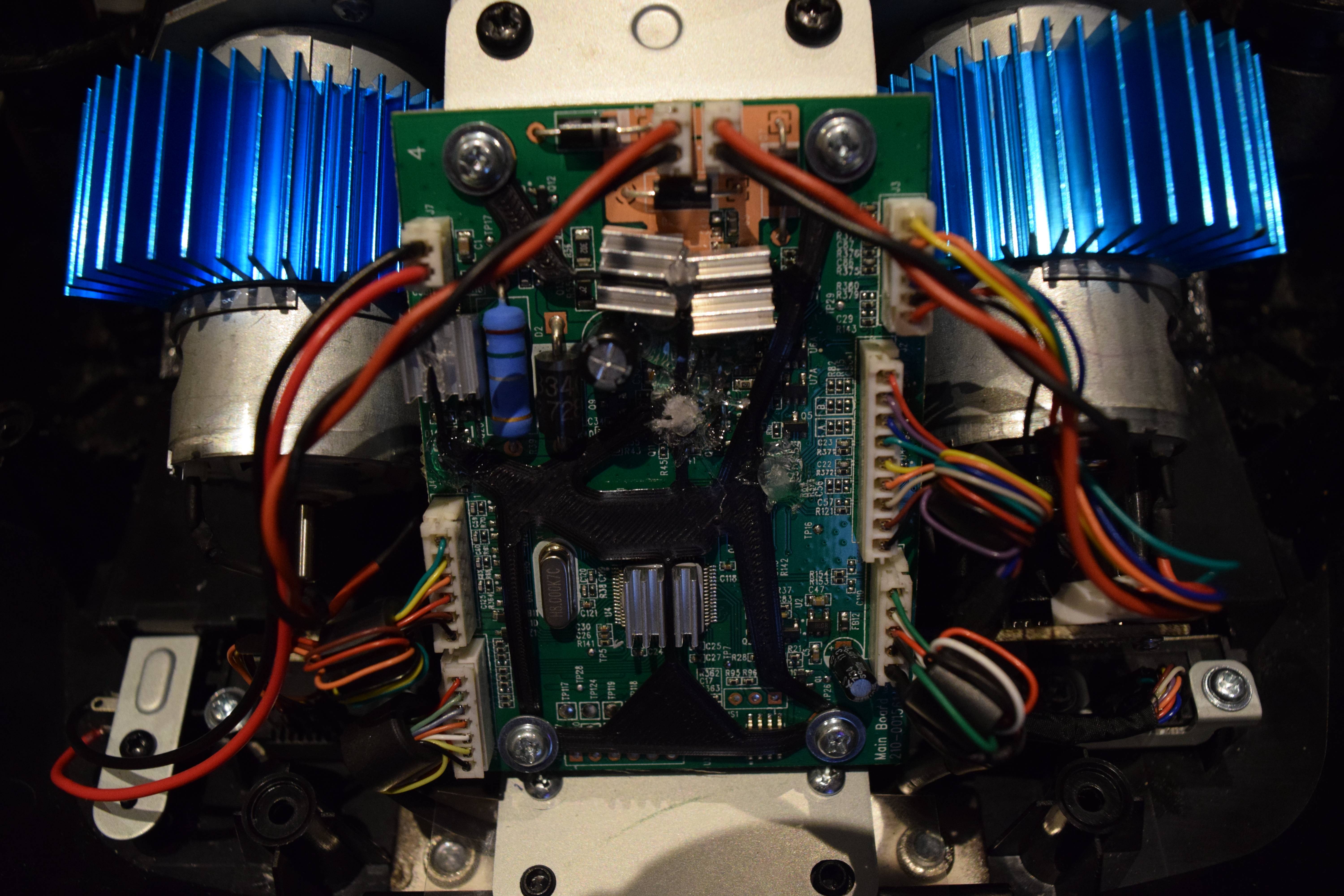
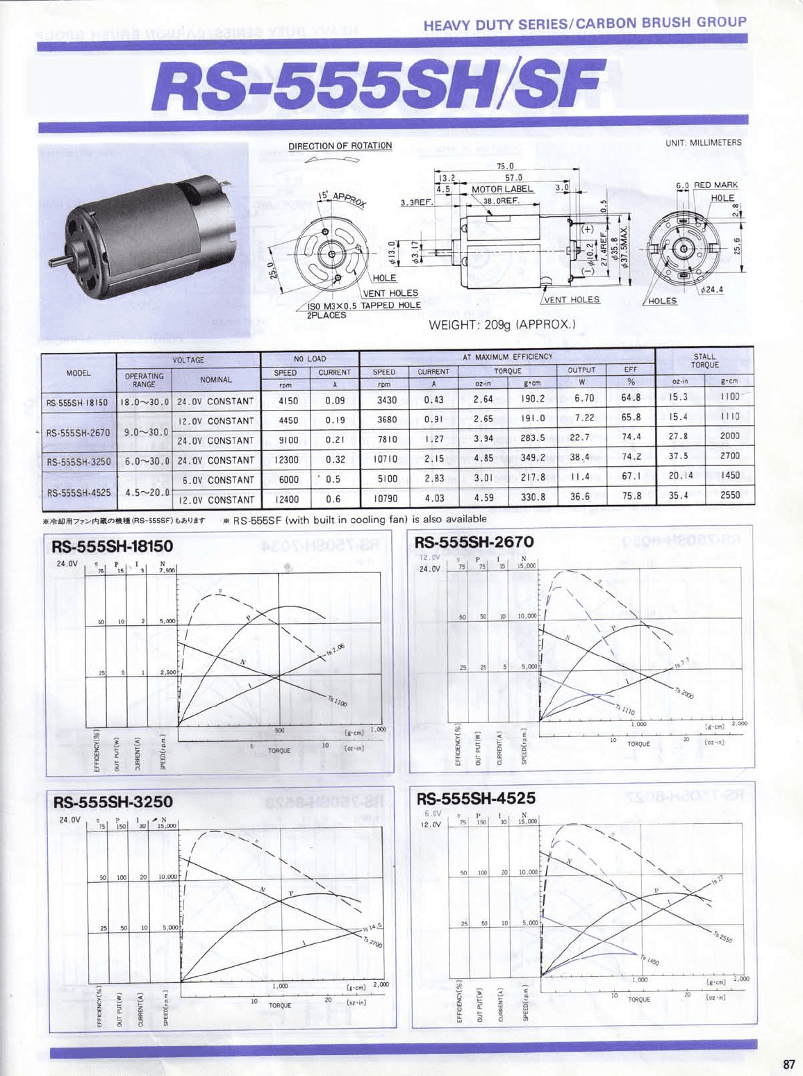
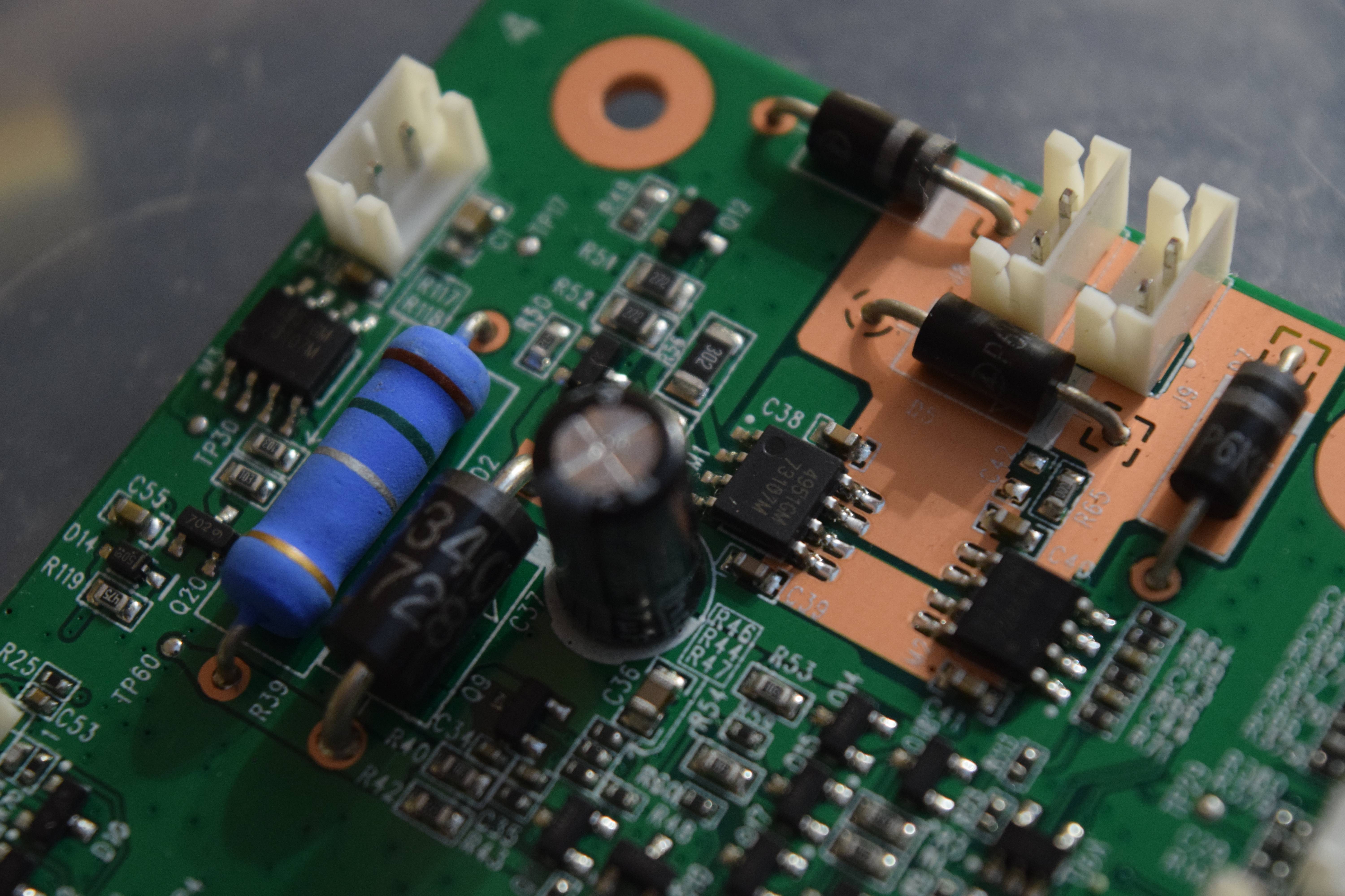
I was looking at the specs on the stock motor FETS, they are rated at 60v and 3.4a, which should be absolutely fine for the 18150 motors as they max out at 2.06a each. However, the single FET that looks like it controls the entire power supply is only rated at 3.5a is a slight concern, as the two bigger motors will be above that limit at peak amp draw. The bigger, 2670 motors that max out at 7.7a, will absolutely blow up all of the stock FETS, light your house on fire and probably open up a black hole, distorting space and time, resulting in humans never evolving to the dominant species or just earths destruction.
@protomor Did you notice any difference in either the center dead zone or lack of minor details since the 18150 motors operation range is 18-30v rather than 12-24v for stock? Did you notice the single FET getting hotter or a burning smell from anything?
The voltage of the new motors may not be a huge issue for me as I mostly play iRacing and can set the minimum force higher, after I test it with the "wheel check" utility. For instance, right now, according to the software, my minimum force on my G29 is 1-2%, my G27 is 16-20%. I'd be interested to see what these motors will test out at.
For anyone who is better with electronics than me and to avoid the destruction of mankind: What would be the appropriate MOSFETs to use for the 2670 motors ? I understand how MOSFETs operate but that is about it. I would think I would need something that can handle at least 40v, 20a for the single FET, and 10a for the motor FETs.


 . Feel free to ask any questions.
") )) I will soon be getting the new motors and mosfets and if everything goes to plan then i should see a nice increase.
)) I will soon be getting the new motors and mosfets and if everything goes to plan then i should see a nice increase.