Somebody have Fanatec Shifter SQ Internal Structure?

  • Thread starter Thread starter hfjj555
  • 11 comments
  • 1,527 views
The page for the shifter on Fanatec's site is a decent representation. They have a sort of cutaway view of it.

I didn't take pictures of the one I had, though I remember it well enough. Is there something in particular you wanted to know?
 
The page for the shifter on Fanatec's site is a decent representation. They have a sort of cutaway view of it.

I didn't take pictures of the one I had, though I remember it well enough. Is there something in particular you wanted to know?


I specifically remember seeing SOME one had taken one apart. Could have Sworn it was you jon, Guess I am mistaken.
 
Oh I had it apart, I even fixed it because wires had come loose. :) I just didn't take any photos of it, unfortunately. I remember it exactly though.
 
Just to add...

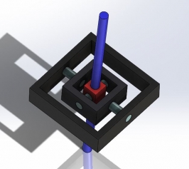
It's a gimbal arrangement. (You'll have to google it, I couldn't find a suitable picture)

Two micro-switches sense either forward or backward position and are actuated by the outer portion of the gimbal rotating on its axis.
A pot or hall sensor (looked like a pot to me) senses left/right movement and is actuated by the inner portion of the gimbal being rotated on its axis.
The gates are located in the bottom on the shifter body and just looks like a gated guide for the end of the shifter rod.
The "in gear" feeling is provided by a ball detent, much like the TH8RS. As the outer portion of the gimbal rotates, it moves a plate with detents in it across the ball detent. The plate is removable. The ball detent is adjustable.
Side to side tension could be adjusted by swapping the torsion spring out for a stronger one.

As for the circuit, it's only complex enough to provide a specific voltage output when in R, 1, 3, 5, 7 or 2, 4, 6, based on the switch pressed. The left/right voltage is provided by the pot output.

Anything else? :)
 
Here, this is a gimbal arrangement. In the case of the shifter, the outer shell/base would be the outer ring in this pic.
 

Attachments

  • Capture.JPG
    Capture.JPG
    27.8 KB · Views: 7
It's set up like this, basically:

screw-spring-ball-detent

When you screw in the screw, it puts more pressure on the spring/ball, causing the detent to require more force. It's a design that will wear out over time, just like the TH8RS. A better design would be a spring loaded roller-bearing. Ponder that. ;)

Here is a roller-bearing design: http://www.hux.net.au/?cat=31 (scroll down a little)

shifter_mounted.jpg
 
Is this your own work Jon?? Are you branching out into the shifter market?

Sorry I should have read the link first lol
 
Is this your own work Jon?? Are you branching out into the shifter market?

No, that is a guy that's been doing stuff like this for quite awhile. Take a look through his blog, there are some interesting things in there. Here's the base blog: http://www.hux.net.au/

Edit: That said, if I WERE to design a shifter with any kind of detent, either gated or sequential, it would use a roller bearing design.
 
Back