I've got another one.
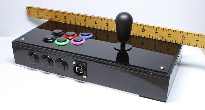
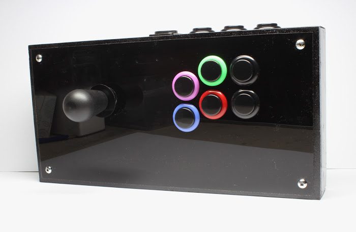
6 x 12 inches. It's just gettin' smaller and smaller.
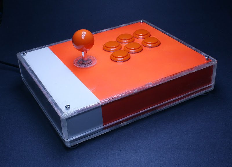
Made it super small to have around my computer for small games so I won't need that orange one anymore. Small games meaning light gaming, meaning I don't need it to be super comfortable or ergonomic, thus I can push the dimensions to a tighter squeeze.
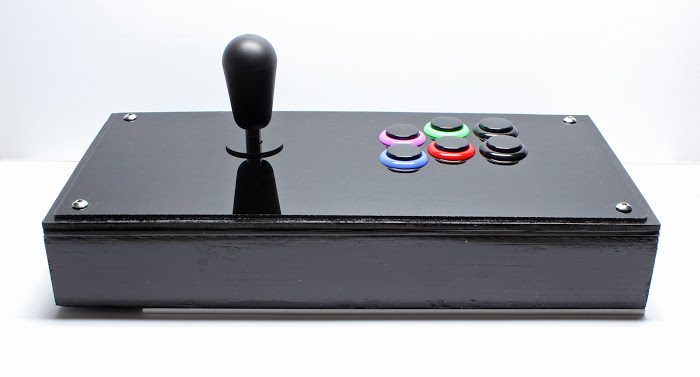
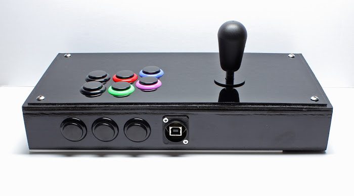
See that button colour arrangement? Playstation face buttons. Simple as that.
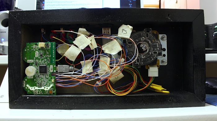
Does it work on a Playstation though?
Why yes it does. In that last stick I made (scroll up a few posts), I gutted my friend's old stick for parts, but I put in a new PCB so the old one was no longer in use. So I took it since it was small and it gave me an excuse to use that Neutrik USB A/B female adaptor plug you see in the second photo.
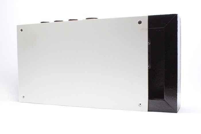
The least prettiest side of it all, unpainted styrene. Two reasons for what I did:
1) I didn't paint it black, because I learned from the black controller (last page) having paint rest on the tender warmth of your thighs is not cool, and everything just scratches eventually.
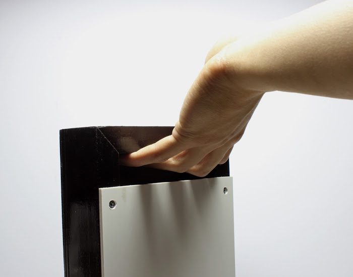
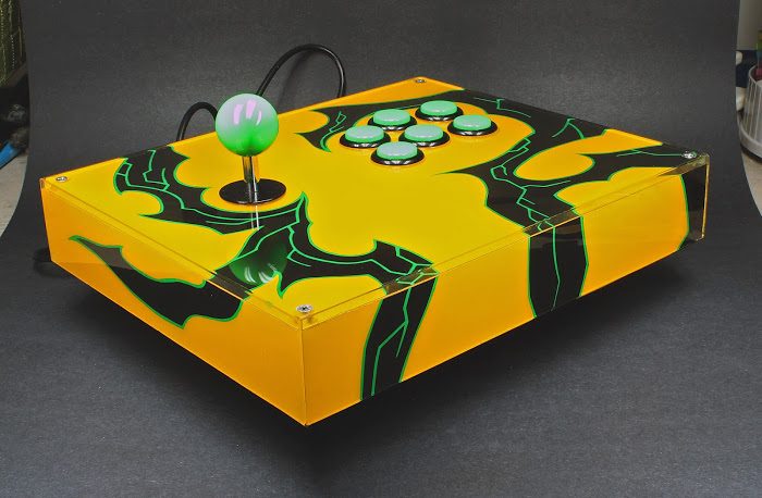
2) It doesn't match the perimeter of the case because it creates a flush handle:
A handle without having something stick out. It works like a charm on the Kemonojo, so I'm doing it again. Plus, I have it hanging on a hook that's attached to the inside leg of my computer table. Tidy and close by.
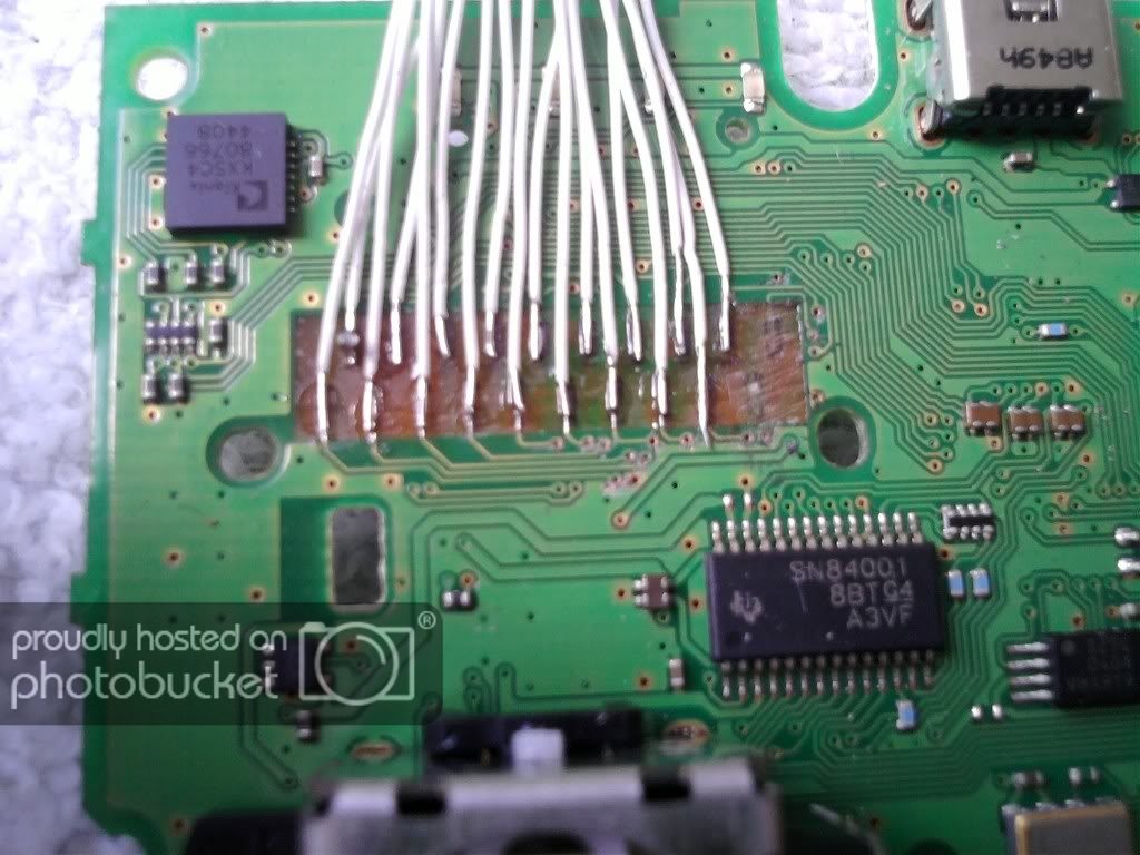
") The blue and orange wires on the soundcard are soldered to the microphone jack, it's also a standard TRS pinout so it's pretty straight forward
The blue and orange wires on the soundcard are soldered to the microphone jack, it's also a standard TRS pinout so it's pretty straight forward 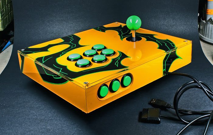
") . It's about 170cms tall, built with a solid pine construction and a metal throwing arm (because it snapped its timber one.) It took months to make and when all was said and done it threw a field hockey ball nearly 200 meters
. It's about 170cms tall, built with a solid pine construction and a metal throwing arm (because it snapped its timber one.) It took months to make and when all was said and done it threw a field hockey ball nearly 200 meters  . Crazy to think I was allowed to build and test something so dangerous at school