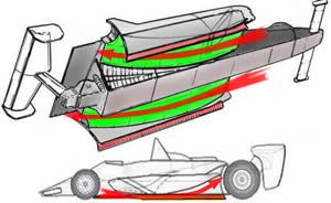
Bernoulli gives a good general idea, but you need to look at more than the ground clearance. Since tires work on slip angle, the car will also yaw in corners. Besides area ratios, curvature radius also changes air pressure. The yaw of the car can create different low pressure zones. What eran said about the downforce vector change direction is important to take into account because pressure is purely a normal force. It will only exert a force perpendicular to the point it's acting on. If the wing isn't level, you will get a side force. In your drawing it's lowering the car's turning ability.
Finding the optimum would take CFD or wind tunnel testing. It would also require a more finalized designed as everything would be geometry sensitive.
Right now it's just a concept, or at least that's how I was presenting it. There is a lot of room to be flexible. A more conservative design could be made by enlarging the sidepods, allowing for more internal room. A thicker center airfoil section could also provide room for a more centralized engine, etc. We could also do something more like the Lotus 79 and use two center tunnels on either side of a low center section.
The design in its current form is pretty extreme, but I still doable in my opinion. Before ruling it out we need more specifics like required driver and engine space, etc.

 Seriously though, thank you very much. 👍


 )
)


") I'm thinking a system of wires could be used, it would connect nicely to the maritime theme
I'm thinking a system of wires could be used, it would connect nicely to the maritime theme