Possible source of CSP load cells.

  • Thread starter racer_x124
  • 88 comments
  • 27,831 views
I changed polarity also but didnt change anything, whats going on?
did you followed the wiring just like in first page? I tried the first time to do it without changing the order (putting red in the middle, yellow left and black right) and it didn't worked, so i went back and followed back, step by step the guide. At least i worked, but i think i got a bunch of faulty sensor, most of them work for half an our, then they start to brake on their own or introduce an huge deadzone. I ended up by ordering 2 official load cell, it should be at my home by friday, but it helped me to have my csp "functional" for nearly 8/9 months
 
Found the problem, it was some time ago (order from china takes some time) i had dissambled the pedals and i remembered that one of the jacks went off when i pulled the cable and i put it back in wrong orientation so ground and signal were wrong.
 
Found the problem, it was some time ago (order from china takes some time) i had dissambled the pedals and i remembered that one of the jacks went off when i pulled the cable and i put it back in wrong orientation so ground and signal were wrong.
I'm glad that everything works fine again!

Ciao!
Ignazio
 
Hi, thanks for the guides here. I just recently got my replacement load cells but couldn't find any videos showing what best to remove in the Elites to install them. Can I install them without removing the pedals from the frame (ie. from the top only)? Hope someone can share a video for reference. Thanks
 
Hi, thanks for the guides here. I just recently got my replacement load cells but couldn't find any videos showing what best to remove in the Elites to install them. Can I install them without removing the pedals from the frame (ie. from the top only)? Hope someone can share a video for reference. Thanks


Make it easy on yourself, Un mount them. It can be done from the top but you have to know what your doing and what/where your plugging in. Stock wires dont leave much for fudge room.
 
Make it easy on yourself, Un mount them. It can be done from the top but you have to know what your doing and what/where your plugging in. Stock wires dont leave much for fudge room.
Yeah, I could do that, was just checking if its practical. What woukd be next after unmounting from the frame, pull out the shaft, and remove the strength dial? Possibly any video or pics posted? Just want to be sure as it took so long to get replacements and never worked on the Elites before, just dont want to mess things up. Thanks
 
Im not familiar with Elite's, but they should be the same as the V2's.....Flip the pedals over, Pull the wire from the circuit board (CAREFULLY), Loosen the 2 screws on the sides of the load cell and replace. You dont need to touch the load cell amp.
 
Im not familiar with Elite's, but they should be the same as the V2's.....Flip the pedals over, Pull the wire from the circuit board (CAREFULLY), Loosen the 2 screws on the sides of the load cell and replace. You dont need to touch the load cell amp.
BTW, I would also replace the foam (inside the shaft cylinder), any idea if this would be accessible as well? Thanks again.
 
Pull the wire from the circuit board (CAREFULLY)...

This!

I have a second hand set of CSR Elite pedals and the brake pedal stopped working after sliding the pedal assembly a smidge closer to the clutch pedal (did not crimp/damage wire in the process...weird correlation). When I started taking everything apart I found the connectors on the PCB are very tight and I could see the female PCB side starting to move. You must hold the female end firmly and carefully work the male side out (without pulling on the wires) or you could damage the PCB.

From finding this thread (THANK YOU!!!), I've ordered the 4 Weighing Sensor Strain Of Half-bridge Sensors and opted for Micro JST 1.25 3-Pin Connector plug Male Female crimps x 50 sets to skip on the soldering step.

If this works, I may need to place 11 more sensor orders and set up an online storefront! ;)
 
The male/female connectors I referenced above is a bust. I didn't realize that I'd spend $5 but require another $50 to get the specialized crimping tool. =|

Going back to page 1, how do you remove the wires from the JST connector? I don't see how to release them to rearrange to get the appropriate colors. Any help would be appreciated!
 
Push the small pin on 1 side of the Plug, Once removed re bend that clip up. (DONT go too far) then click it back in place where needed.
 
Thanks, I'll give it a try on the OEM load cell.

I ended up buying the PA-09 crimping tool afterall. A new load cell from Fanatec would cost $40 shipped, Prime had the crimp tool for $42. I'm still ahead of the game and maybe I'll get to use this new fancy tool down the road again.
 
Further update for anyone ordering from my above links, and a (possible) confirmation from eKretz's post on 05/14/2014 which no one ever touched on.

Having all of the pieces needed to wire things up correctly, I sat down and went to work stripping and crimping and getting the connectors onto the new load cell. This stuff is TINY!!! :eek:

20160403_113816.jpg
20160403_124010.jpg


When I went to plug in the JST 1.25 connector to the Fanatec PCB I found the female connector to be too small, the pin spacing incorrect and the pin style to be different. This brings me to eKretz's post on page two where he stated the JST ZH was the correct connection, not the regular JST.

This led me to RC Groups and Micron Wings' website where the JST connections are compared and detailed.

JST 1.25 3 pin vs. JST ZH 1.50 3 pin

The regular JST 1.25 connector is a bladed design and the JST ZH is a rounded pin design. My digital caliper seems to confirm the (my) PCB connections are the ZH proportions so off to Hong Kong again for the ZH connectors. I have to justify my PA-09 purchase! LOL
 
Last edited:
I can confirm the JST ZH (1.5 x3) is the correct fitment for my CSR Elite pedals PCB.

That said, I'm having no luck getting the pedal to register. =|

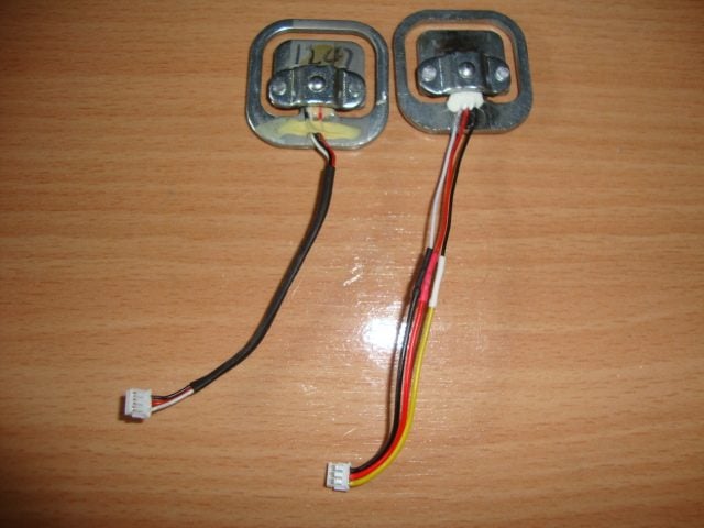
As shown on the left in Jadran's post...

dsc09110.jpg


...the original load cell is Black White Red at the load cell and Black Red White at the connector, locking pins up (same orientation as above). Since I'm putting my own connectors on, and the colors are in different placements...it should look something like this, no?

Black White Red (original load cell)
Black Red White (connector end)

Becomes...

White Red Black (eBay load cell)
White Black Red (connector end)

Not well versed in the electrical side of things, but looking at Jadran's example on the right, that's basically a like color to like color connection is it not (no wires are crossed from load cell to the connector)? Meaning I should bring White Red Black down straight to the connector block?
 
From the outside of the board the wires are: black, red, white. Either I had them backwards of this new sensor has them backwards.

This quote also suggests it being a straight shot from the load cell...guess I'll look at my crimp technique more closely tonight and see what happens.
 
Just a heads up, I was having intermittent load cell problems with my CSPv2s, it would randomly start to register braking input, and it would fluctuate. The problem was with the connection itself, those little plugs aren't the most resilient things in the world.

Because the load cell on these go fairly regularly, sometimes in a race, and changing them is a complete pain I actually used some spare M12 leads I had lying around soldered the wires from the female one directly on to the circuit board pins. I then soldered the male one to the load cell wires. I will make a couple of these up so that if the load cell were to fail in an endurance race it would simply be a matter of unplugging the load cell, swapping it, and plugging it back in again (and recalibrating if needed).

DSC_0013_zpso3eeidxh.jpg


Having the plug at an easier to get at location makes for a much faster swap, and these connections are more resilient.
 
I'm at a loss as nothing registers in the Game Controllers properties page with any of these new load cells. If I plug the clutch into the brake port on the PCB travel registers, so the PCB is not at fault.

20160414_210055.jpg

I know this isn't in the right orientation (below)...it was for speed of removal during testing. I've flipped it around to the correct orientation, which allows the pin to seat better on the top of the sensor, with no change in the testing results.

20160414_210225.jpg


Combos attempted...

white red black
black red white
red black white
white black red
black white red
red white black

Don't see what I'm missing here... :odd:
 
This is the crimp procedure I used to achieve the above.

Here I've stripped away the end of the wire
IMG_0522.JPG

I've taken half of the exposed wire and double it back unto itself to gain a larger crimping footprint
IMG_0526.JPG

I've aligned the end connector into the (specialized) crimping tool 1.4 slot
IMG_0528.JPG

I've inserted the wire putting the insulation up to the edge of the tool, allowing only the exposed metal to be crimped
IMG_0530.JPG

Backside of the toll with the "plug" end peeking out
IMG_0531.JPG

Wire crimp done
IMG_0532.JPG

Inserting the connector back into the tool and getting ready to roll the two vertical blades over and into the insulating layer
IMG_0534.JPG

Crimped and secured in the insulating layer
IMG_0536.JPG

Connector fully crimped
IMG_0540.JPG

All wires inserted into JST ZH 1.5 3 pin connector
IMG_0543.JPG
 
Silly question but have you made sure the pins are actually making contact with the terminal crimps? Like does it feel secure on the plug?

(Try putting each crimp on the pins themselves without the white plug part)

Edit:

Oh hey I just read your post again regarding the colours. eBay load cells use the same colours as the original, as in if you were to cut the lead off and crimp/solder on to existing wires then you would go colour to colour.

Only time you need to muck around with colours was if you were to use one of those pre made leads with the yellow wire.

Seeing as how you have tried all combinations it's likely not that, I just thought I would let you know as you had it a little mixed up in one of your previous posts.

Also, unplug the pedals and plug back in.
 
Last edited:
I can't imagine it isn't making contact from the feeling I get when seating/unseating on the PCB. It is a nice tight fit. I'll try the one on one connection tonight to verify though...thanks.

The color arrangement exiting my OEM load cell, and eBay load cell, matches Jadran's picture above to a T.

Each time I try a new combination, the pedals are unplugged when making the PCB connection and unplugged again when disconnecting from the PCB.

If something doesn't pop up as being the error in my procedure/technique, I'll have to order a load cell from Fanatec and just eat the money spent on the DIY side.
 
Last edited:
Leads to pin have good connection. No change. Pulled the plug and ordered from Fanatec. Will report back when I get the part and can test things again.
 
Thinking back now, I also had my Ebay cells "not work" on the first go. And had to swip swap one of the wires as it didn't match what racer_x124 had ....as to which i cant remember as when i realized the mistake, I corrected all 4 of them. Want me to take a pic of pin location and what wire's going where ?
 
Back